Columns
Shortcut Column
The Shortcut Column is used to calculate the minimum reflux in a distillation column by Fenske-Underwood-Gilliland (FUG) method.
- The shortcut column model have following connection ports:
- Three Material Streams: feed, distillate and bottoms
- Two Energy Streams: condenser duty and reboiler duty
- The results are:
- Minumum Reflux Ratio
- Actual Reflux Ratio
- Total Number of Stages
- Feed Stage
- Condenser and Reboiler Duty
- Liquid and Vapor flows in Rectification and Stripping section
- Pressure and Temperature of Condenser and Reboiler
To simulate a shortcut column, following calculation parameters must be provided:
- Condenser Type
Ctype- Heavy Key Component
HKey- Light Key Component
LKey
Among the above variables, first one Ctype is of type parameter String. It can have either of the sting values among following:
Total: To indicate that the condenser is Total CondenserPartial: To indicate that the condenser is Partial Condenser
The other two variables are of type parameter Integer. These are to indicate high key and low key component. They can be indicated by the corresponding indices from variable C[Nc].
During simulation, their values can specified directly under Column Specifications by double clicking on the shortcut column model instance.
Additionally, following input for following variables must be provided:
- Reflux Ratio
RR- Heavy Key Component Mole Fraction in Distillate
x_pc[2, LKey]- Light Key Component Mole Fraction in Bottoms
x_pc[3, HKey]- Condenser Pressure
Pcond- Reboiler Pressure
Preb
These variables are declared of type Real. During simulation, value of all these variables need to be defined in the equation section.
Simulating a Shortcut Column
Equimolar amount of feed consisting of benzene and toluene at 100 mol/s enters a shortcut column. The feed stream enters at 370 K and 101325 Pa.
Below listed points are the step by step explaination as to how to create and simulate this shortcut column problem.
Create a package named
ShortcutColumn.Create a model named
MSinsideShortcutColumn. This is to extendMaterialStreammodel.Extend the model
MaterialStreamand necessary property method fromThermodynamicPackages.extends Simulator.Streams.MaterialStream; extends Simulator.Files.ThermodynamicPackages.RaoultsLaw;Create another new model named
ShortcutinsideShortcutColumn. This is to extendShortcutColumnmodel.Extend the model
ShortcutColumnfromUnitOperationspackage and necessary property method fromThermodynamicPackages.extends Simulator.Streams.MaterialStream; extends Simulator.Files.ThermodynamicPackages.RaoultsLaw;Create another new model named
ShortcutSimulationinsideShortcutColumn.Similar to the
MaterialStreamexample model, importChemsepDatabaseand create variables for the compounds which are to be used fromChemsepDatabase.import data = Simulator.Files.ChemsepDatabase; parameter data.Benzene benz; parameter data.Toluene tol;Define variables for Number of components
Ncand component arrayC. Also assign the variables created for the compounds to the component array.parameter Integer Nc = 2; parameter Simulator.Files.ChemsepDatabase.GeneralProperties C[Nc] = {benz, tol};9. Now, create three instances of the
MaterialStreammodelMSas we require one material stream which will go as feed and two streams that comes out as distillate and bottoms. To do this, open diagram view ofShortcutSimulationmodel, drag & dropMSthrice as shown in fig. Name the instances asS1,S2andS3.
Now, create two instances of
EnergyStreammodel. For this, drag and drop theEnergyStreammodel twice available underStreams. Name the instance asE1andE2.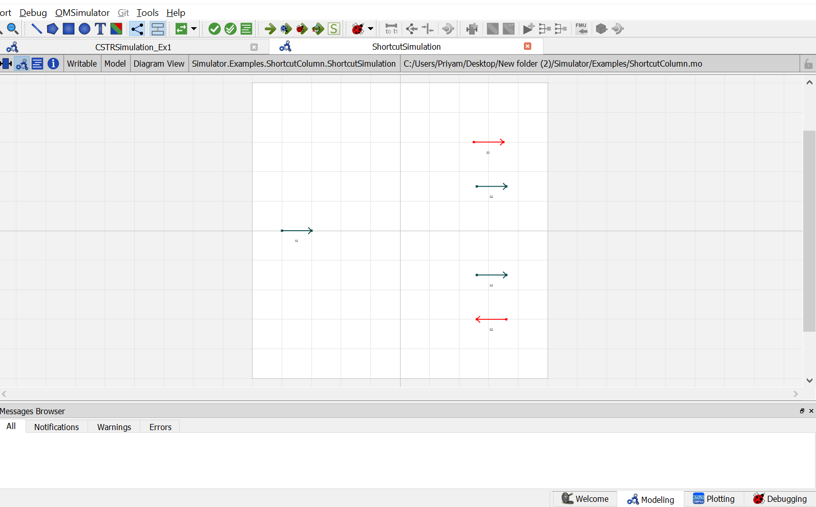
Now, create an instance of the
ShortcutColumnmodelShortcut. Switch to the diagram view ofShortcutSimulationmodel, drag & dropShortcut. A pop up will appear asking the name of the component. Enter the name asB1.
12. Now double click on
S1. Component Parameters window opens. Go to Stream Specifications tab. There are two parameterNcandCfor which the values are to be entered. As the value forNcandCare already declared earlier in step 6 while defining the variables, these variables are passed here instead of the values. Repeat this for the other two material streams.
13. Now double click on
B1. Component Parameters window opens. Go to Column Specifications tab and enter the values for parameters as mentioned below:
NcandCcan be entered same as material stream
HKeyrepresents the Heavy Key Component. Enter the index value of heavy key component from the arrayC[Nc]. Toluene is the heavy key whose index value inC[Nc]is2.
LKeyrepresents the Light Key Component. Enter the index value of light key component from the arrayC[Nc]. Benzene is the light key whose index value inC[Nc]is1.
Ctyperepresents the type of condenser. As per the problem statement, total condenser is used. So enterCtypeasTotal.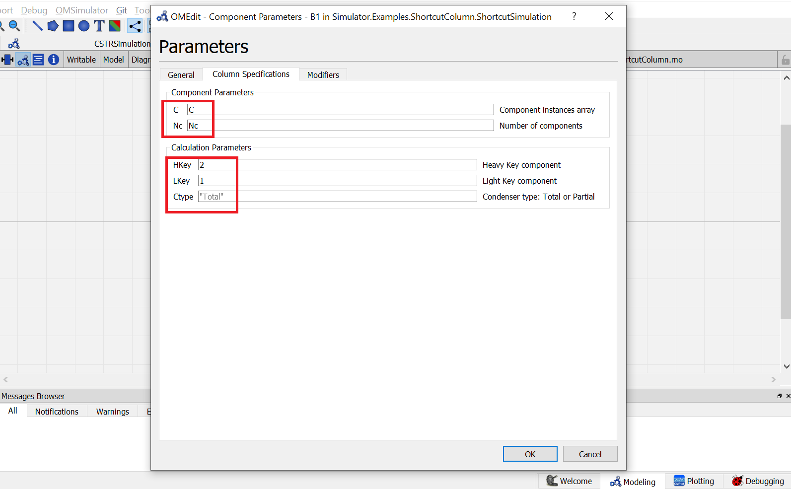
Switch to text view. Following lines of code will be autogenrated
Simulator.Examples.ShortcutColumn.MS S1(Nc = Nc, C = C) annotation( ...);
Simulator.Examples.ShortcutColumn.MS S3(Nc = Nc, C = C) annotation( ...);
Simulator.Examples.ShortcutColumn.MS S2(Nc = Nc, C = C) annotation( ...);
Simulator.Streams.EnergyStream E1 annotation( ...);
Simulator.Streams.EnergyStream E2 annotation( ...);
Simulator.Examples.ShortcutColumn.Shortcut B1(Nc = Nc, C = C, HKey = 2, LKey = 1) annotation( ...);
Now, connect the streams with unit operations. For this, switch back to Diagram view.
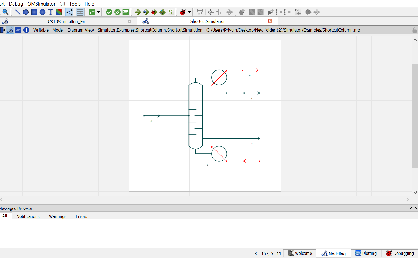
Switch to text view. Following lines of code will be autogenrated under
equationsectionconnect(B1.En1, E1.In) annotation( ...); connect(E2.Out, B1.En2) annotation( ...); connect(B1.Out2, S3.In) annotation( ...); connect(B1.Out1, S2.In) annotation( ...); connect(S1.Out, B1.In) annotation( ...);Specify the pressure, temperature, component mole fractions and molar flow rate for the feed stream
S1.P = 101325;
S1.T = 370;
S1.x_pc[1, :] = {0.5, 0.5};
S1.F_p[1] = 100;
Now specify the variables for shortcut column as explained earlier. So specify reflux ratio, mole fraction of heavy key component in distillate, mole fraction of light key in bottoms, condenser pressure and reboiler pressure.
B1.Preb = 101325; B1.Pcond = 101325; B1.x_pc[2, B1.LKey] = 0.01; B1.x_pc[3, B1.HKey] = 0.01; B1.RR = 2;
This completes the
ShortcutColumnpackage. Now click onSimulatebutton to simulate theShortcutSimulationmodel. Switch to Plotting Perspective to view the results.Note
You can also find this package named
ShortcutSimulationin theSimulatorlibrary underExamplespackage.
Distillation Column
The Distillation Column is used to separate the component mixture into component parts or fraction based on difference in volatalities.
The distillation column model have following connection ports: Material Streams: any number of feed streams and two products (distillate and bottom) Two Energy Streams: condenser duty and reboiler duty
The results are:
- Molar flow rate of Distillate and Bottoms
- Composition of Components in Distillate and Bottoms
- Condenser and Reboiler Duty
- Stagewise Liquid and Vapor Flows
- Temperature Profile
To simulate a distillation column, following calculation parameters must be provided:
- Number of Stages
Nt- Number of Feed Streams
Ni- Feed Tray Location
InT_s- Condenser Type
Ctype
All the variables are of type parameter Real except the last one (Ctype) which is of type parameter String. It can have either of the sting values among following:
Total: To indicate that the condenser is Total CondenserPartial: To indicate that the condenser is Partial Condenser
During simulation, their values can specified directly under Column Specifications by double clicking on the column instance.
Additionally, following input for following variables must be provided:
- Condenser Pressure
Pcond- Reboiler Pressure
Preb- Top Specification
- Bottom Specification
Any one of the following variables can be considered as Top Specification:
- Reflux Ratio
RR- Molar Flow rate
F_p[1]
Any one of the following can be considered as Bottoms Specification:
- Molar Flow rate
F_p[1]- Mole Fraction of Component
x_pc[1,:]
These variables are declared of type Real and therefore all these variables need to be declared in the equation section while simulating the model.
Simulating a Distillation Column
Below listed points are the step by step explaination as to how to create and simulate this distillation column problem.
Create a package named
Distillation.Create a model named
MSinsideDistillation. This is to extendMaterialStreammodel.Extend the model
MaterialStreamand necessary property method fromThermodynamicPackages.extends Simulator.Streams.MaterialStream; extends Simulator.Files.ThermodynamicPackages.RaoultsLaw;Create another new model named
CondenserinsideDistillation. This is to extendCondmodel fromDistillationColumnpackage.Extend the model
Condavailable underDistillationColumnpackage fromUnitOperationsand necessary property method fromThermodynamicPackages.extends Simulator.UnitOperations.DistillationColumn.Cond; extends Simulator.Files.ThermodynamicPackages.RaoultsLaw;Create another new model named
TrayinsideDistillation. This is to extendDistTraymodel fromDistillationColumnpackage.Extend the model
DistTrayavailable underDistillationColumnpackage fromUnitOperationsand necessary property method fromThermodynamicPackages.extends Simulator.UnitOperations.DistillationColumn.DistTray; extends Simulator.Files.ThermodynamicPackages.RaoultsLaw;Create another new model named
ReboilerinsideDistillation. This is to extendRebmodel fromDistillationColumnpackage.Extend the model
Rebavailable underDistillationColumnpackage fromUnitOperationsand necessary property method fromThermodynamicPackages.extends Simulator.UnitOperations.DistillationColumn.Reb; extends Simulator.Files.ThermodynamicPackages.RaoultsLaw;Create another new model named
DistColumninsideDistillation. This is to extendDistColmodel fromDistillationColumnpackage.Extend the model
DistColavailable underDistillationColumnpackage fromUnitOperations.extends Simulator.UnitOperations.DistillationColumn.DistCol;Along with this create an instance of
Condensermodel extended earlier in step 4 and 5. Pass theCondenser condenser(Nc = Nc, C = C, Ctype = Ctype, Bin = Bin_t[1]); Reboiler reboiler(Nc = Nc, C = C, Bin = Bin_t[Nt]); Tray tray[Nt - 2](each Nc = Nc, each C = C, Bin = Bin_t[2:Nt - 1]);
Create another new model named
DistillationSimulation_Ex1insideDistillation.Similar to the
MaterialStreamexample model, importChemsepDatabaseand create variables for the compounds which are to be used fromChemsepDatabase.import data = Simulator.Files.ChemsepDatabase; parameter data.Benzene benz; parameter data.Toluene tol;Define variables for Number of components
Ncand component arrayC. Also assign the variables created for the compounds to the component array.parameter Integer Nc = 2; parameter Simulator.Files.ChemsepDatabase.GeneralProperties C[Nc] = {benz, tol};9. Now, create three instances of the
MaterialStreammodelMSas we require one material stream which will go as feed and two streams that comes out as distillate and bottoms. To do this, open diagram view ofShortcutSimulationmodel, drag & dropMSthrice as shown in fig. Name the instances asS1,S2andS3.
Now, create two instances of
EnergyStreammodel. For this, drag and drop theEnergyStreammodel twice available underStreams. Name the instance asE1andE2.Now, create an instance of the
ShortcutColumnmodelShortcut. Switch to the diagram view ofShortcutSimulationmodel, drag & dropShortcut. A pop up will appear asking the name of the component. Enter the name asB1.12. Now double click on
S1. Component Parameters window opens. Go to Stream Specifications tab. There are two parameterNcandCfor which the values are to be entered. As the value forNcandCare already declared earlier in step 6 while defining the variables, these variables are passed here instead of the values. Repeat this for the other two material streams.13. Now double click on
B1. Component Parameters window opens. Go to Column Specifications tab and enter the values for parameters as mentioned below:
NcandCcan be entered same as material stream
HKeyrepresents the Heavy Key Component. Enter the index value of heavy key component from the arrayC[Nc]. Toluene is the heavy key whose index value inC[Nc]is2.
LKeyrepresents the Light Key Component. Enter the index value of light key component from the arrayC[Nc]. Benzene is the light key whose index value inC[Nc]is1.
Ctyperepresents the type of condenser. As per the problem statement, total condenser is used. So enterCtypeasTotal.
Switch to text view. Following lines of code will be autogenrated
Simulator.Examples.ShortcutColumn.MS S1(Nc = Nc, C = C) annotation( ...);
Simulator.Examples.ShortcutColumn.MS S3(Nc = Nc, C = C) annotation( ...);
Simulator.Examples.ShortcutColumn.MS S2(Nc = Nc, C = C) annotation( ...);
Simulator.Streams.EnergyStream E1 annotation( ...);
Simulator.Streams.EnergyStream E2 annotation( ...);
Simulator.Examples.ShortcutColumn.Shortcut B1(Nc = Nc, C = C, HKey = 2, LKey = 1) annotation( ...);
Now, connect the streams with unit operations. For this, switch back to Diagram view.
Switch to text view. Following lines of code will be autogenrated under
equationsectionconnect(B1.En1, E1.In) annotation( ...); connect(E2.Out, B1.En2) annotation( ...); connect(B1.Out2, S3.In) annotation( ...); connect(B1.Out1, S2.In) annotation( ...); connect(S1.Out, B1.In) annotation( ...);Specify the pressure, temperature, component mole fractions and molar flow rate for the feed stream
S1.P = 101325;
S1.T = 370;
S1.x_pc[1, :] = {0.5, 0.5};
S1.F_p[1] = 100;
Now specify the variables for shortcut column as explained earlier. So specify reflux ratio, mole fraction of heavy key component in distillate, mole fraction of light key in bottoms, condenser pressure and reboiler pressure.
B1.Preb = 101325; B1.Pcond = 101325; B1.x_pc[2, B1.LKey] = 0.01; B1.x_pc[3, B1.HKey] = 0.01; B1.RR = 2;
This completes the
ShortcutColumnpackage. Now click onSimulatebutton to simulate theShortcutSimulationmodel. Switch to Plotting Perspective to view the results.Note
You can also find this package named
ShortcutSimulationin theSimulatorlibrary underExamplespackage.
Distillation Column
The Distillation Column is used to separate the component mixture into component parts or fraction based on difference in volatalities.
The distillation column model have following connection ports: Material Streams: any number of feed streams and two products (distillate and bottom) Two Energy Streams: condenser duty and reboiler duty
The results are:
- Molar flow rate of Distillate and Bottoms
- Composition of Components in Distillate and Bottoms
- Condenser and Reboiler Duty
- Stagewise Liquid and Vapor Flows
- Temperature Profile
To simulate a distillation column, following calculation parameters must be provided:
- Number of Stages
Nt- Number of Feed Streams
Ni- Feed Tray Location
InT_s- Condenser Type
Ctype
All the variables are of type parameter Real except the last one (Ctype) which is of type parameter String. It can have either of the sting values among following:
Total: To indicate that the condenser is Total CondenserPartial: To indicate that the condenser is Partial Condenser
During simulation, their values can specified directly under Column Specifications by double clicking on the column instance.
Additionally, following input for following variables must be provided:
- Condenser Pressure
Pcond- Reboiler Pressure
Preb- Top Specification
- Bottom Specification
Any one of the following variables can be considered as Top Specification:
- Reflux Ratio
RR- Molar Flow rate
F_p[1]
Any one of the following can be considered as Bottoms Specification:
- Molar Flow rate
F_p[1]- Mole Fraction of Component
x_pc[1,:]
These variables are declared of type Real and therefore all these variables need to be declared in the equation section while simulating the model.
Absorption Column
The Absorption Column is used to separate gas mixture by scrubbing through a liquid solvent.
The absorption column model have following connection ports: Material Streams two feed streams and two products
The results are:
- Molar flow rate of Product streams
- Composition of Components in Product streams
- Stagewise Liquid and Vapor Flows
- Temperature Profile
To simulate an absorption column, the only calculation parameter which must be provided is Number of Stages Nt.
During simulation, its value can specified directly under Column Specifications by double clicking on the column instance.