Pressure Changers
Valve
A Valve is used to simulate the pressure manipulation process of a material stream.
The valve model has two material streams connection ports as:
- feed stream
- outlet stream
To simulate a valve, one of the following variables must be provided:
- Outlet Pressure
Pout- Pressure Drop
Pdel
These variables are declared of type Real. During simulation, value of one of these variables need to be defined in the equation section.
Simulating a Valve
Create a package named
ValveCreate a model named
MSinsideValve. This is to extendMaterialStreammodelExtend the model
MaterialStreamand necessary property method fromThermodynamicPackagesextends Simulator.Streams.MaterialStreams; extends Simulator.Files.ThermodynamicPackages.RaoultsLaw;Create another new model named
ValveSimulationSimilar to the
MaterialStreamexample model, importChemsepDatabaseand create variables for the compounds which are to be used fromChemsepDatabaseimport data = Simulator.Files.ChemsepDatabase; parameter data.Ethanol eth; parameter data.Methanol meth; parameter data.Water wat;Define variables for Number of components
Ncand component array of size NcC[Nc]. Also assign the variables created for the compounds to the component arrayparameter Integer Nc = 3; parameter data.GeneralProperties C[Nc] = {meth, eth, wat};Now, create two instances of the
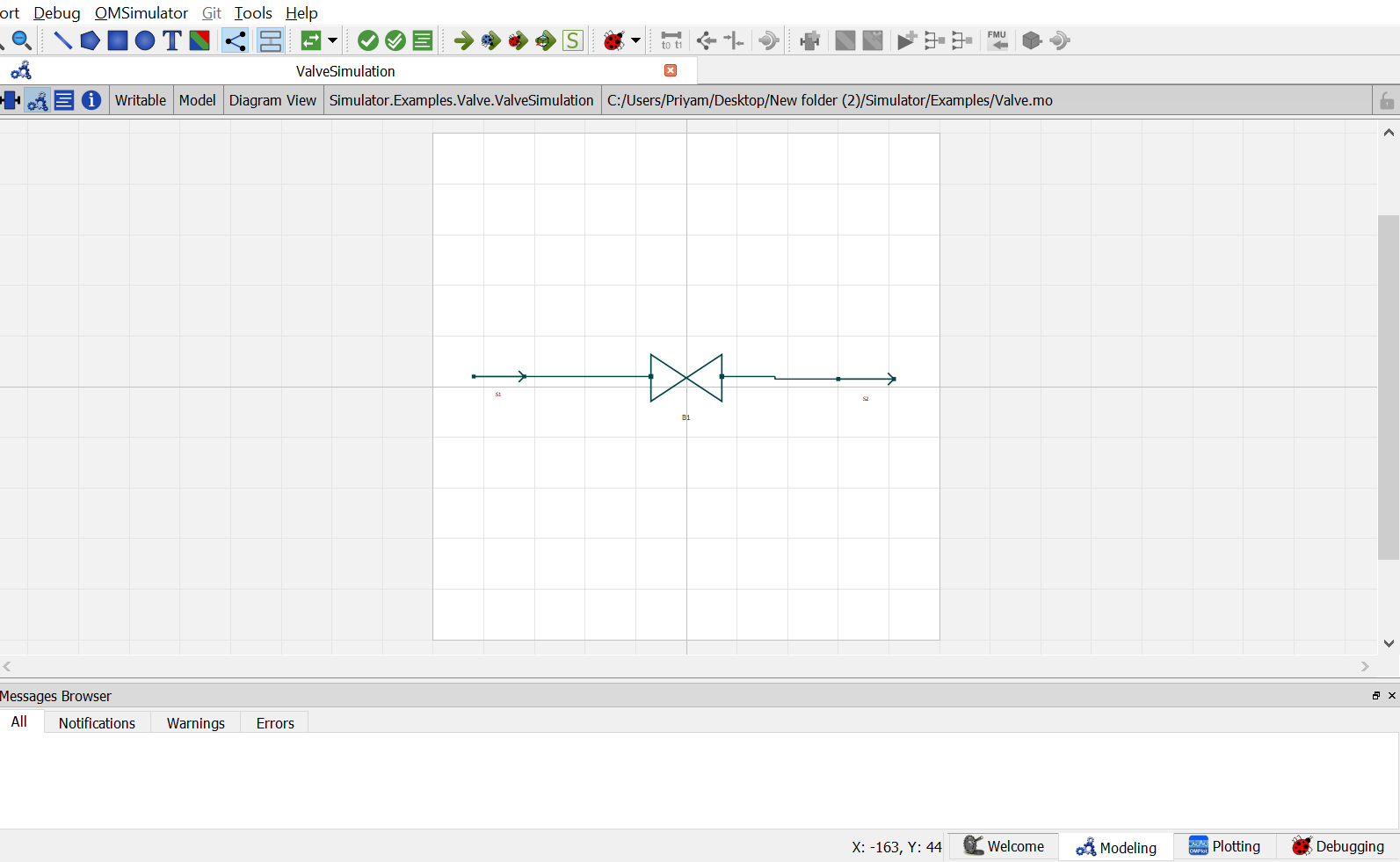
MaterialStreammodelMSas one material stream instance will act as input and the other one will act as output. To do this, open diagram view ofValveSimulationmodel, drag & dropMStwice. Name the instances asS1andS2.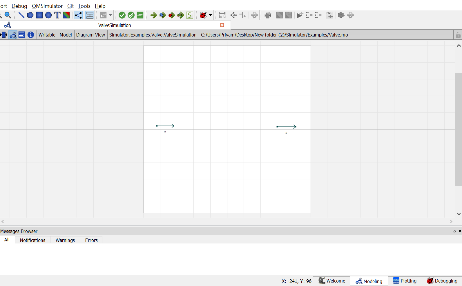
Now, Drag and drop the
Valvemodel available underUnitOperations. Name the instance asB1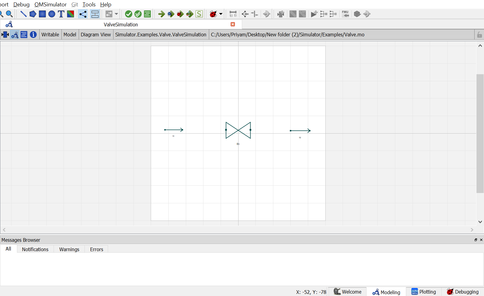
Now double click on
S1. Component Parameters window opens. Go to Stream Specifications tab. There are two parametersC and ``Ncfor which the values are to be entered. As the value forNcandCare already declared earlier in step 6 while defining the variables, these variables are directly passed here instead of the values. Repeat this for remainingoutputinstance as well.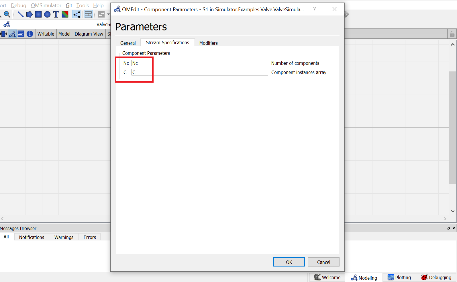
Now double click on
B1. Component Parameters window opens. Go to Valve Specifications tab. Similar to material stream instance, there are two parameters available hereCandNc. Therefore repeat the same step as material stream instances.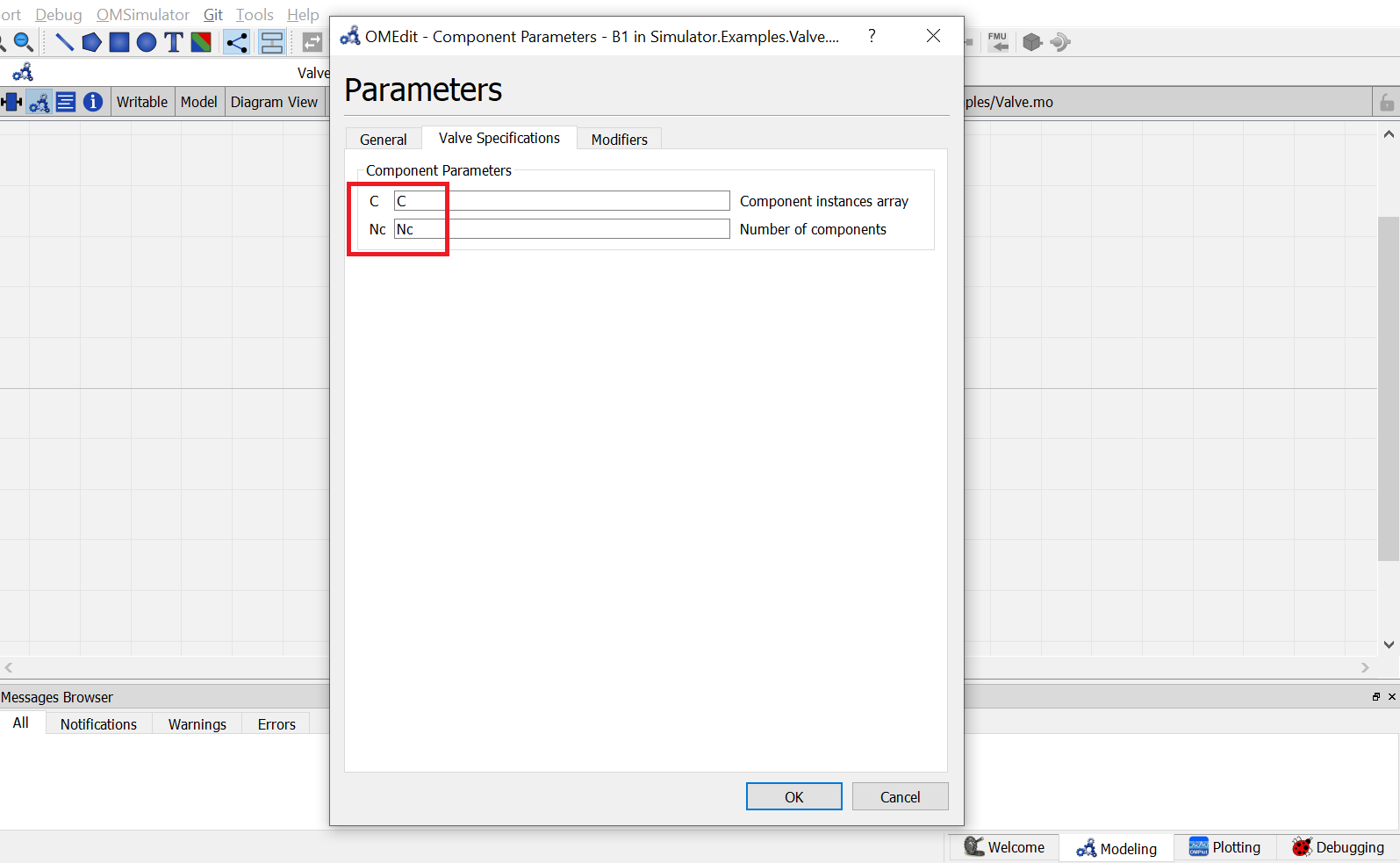
Switch to text view, following lines of code will be autogenerated
MS S1(Nc = Nc, C = C) annotation( ...);
MS S2(Nc = Nc, C = C) annotation( ...);
Simulator.UnitOperations.Valve B1(Nc = Nc, C = C) annotation( ...);
Now, connect the streams with unit operations. For this, switch back to Diagram view.
Switch to text view. Following lines of code will be autogenrated under
equationsectionconnect(B1.Out, S2.In) annotation( ...); connect(S1.Out, B1.In) annotation( ...);Specify the pressure, temperature, component mole fractions and molar flow rate for the inlet material stream
S1.x_pc[1, :] = {0.33, 0.33, 0.34};
S1.P = 202650;
S1.T = 372;
S1.F_p[1] = 100;
Now specify the one of the calculation variables for the valve as mentioned earlier. Here, pressure drop
Pdelis specifiedB1.Pdel = 101325;
- This completes the Valve package. Now click on
Simulatebutton to simulate theValveSimulationmodel. Switch to Plotting Perspective to view the results.
Note
You can also find this package named
Valvein theSimulatorlibrary underExamplespackage.
Centrifugal Pump
A Centrifugal Pump is generally used to provide energy to a liquid material stream. The energy supplied is in form of pressure.
The centrifugal pump model have following connection ports:
Two Material Streams:
- feed stream
- outlet stream
One Energy Stream:
- power required
To simulate a centrifugal pump, Efficiency Eff of the pump should be provided as calculation parameter.
The variable Eff is defined as of type parameter Real.
During simulation, its value can specified directly under Pump Specifications by double clicking on the pump model instance.
Additionally one of the following input variables must be defined:
- Outlet Pressure
Pout- Pressure Increase
Pdel- Power Required
Q
These variables are declared of type Real. During simulation, value of one of these variables need to be defined in the equation section.
Simulating a Centrifugal Pump
Create a package named
PumpCreate a model named
MSinsidePump. This is to extendMaterialStreammodel.Extend the model
MaterialStreamand necessary property method fromThermodynamicPackagesextends Simulator.Streams.MaterialStreams; extends Simulator.Files.ThermodynamicPackages.RaoultsLaw;Create another new model named
PumpSimulationSimilar to the
MaterialStreamexample model, importChemsepDatabaseand create variables for the compounds which are to be used fromChemsepDatabaseimport data = Simulator.Files.ChemsepDatabase; parameter data.Benzene benz; parameter data.Toluene tol;Define variables for Number of components
Ncand component array of size NcC[Nc]. Also assign the variables created for the compounds to the component arrayparameter Integer Nc = 2; parameter data.GeneralProperties C[Nc] = {benz, tol};
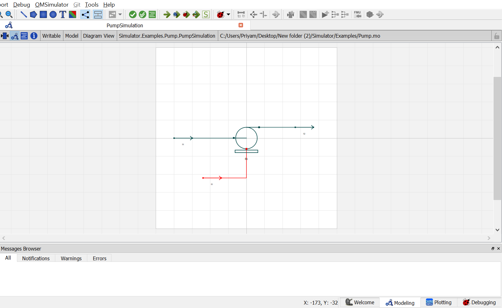
- Now, create two instances of the
MaterialStreammodelMSas one material stream instance will act as input and the other one will act as output.To do this, open diagram view of
PumpSimulationmodel, drag & dropMStwice. Name the instances asS1andS2.Now, Drag and drop the
EnergyStreammodel available underStreams. Name the instance asE1.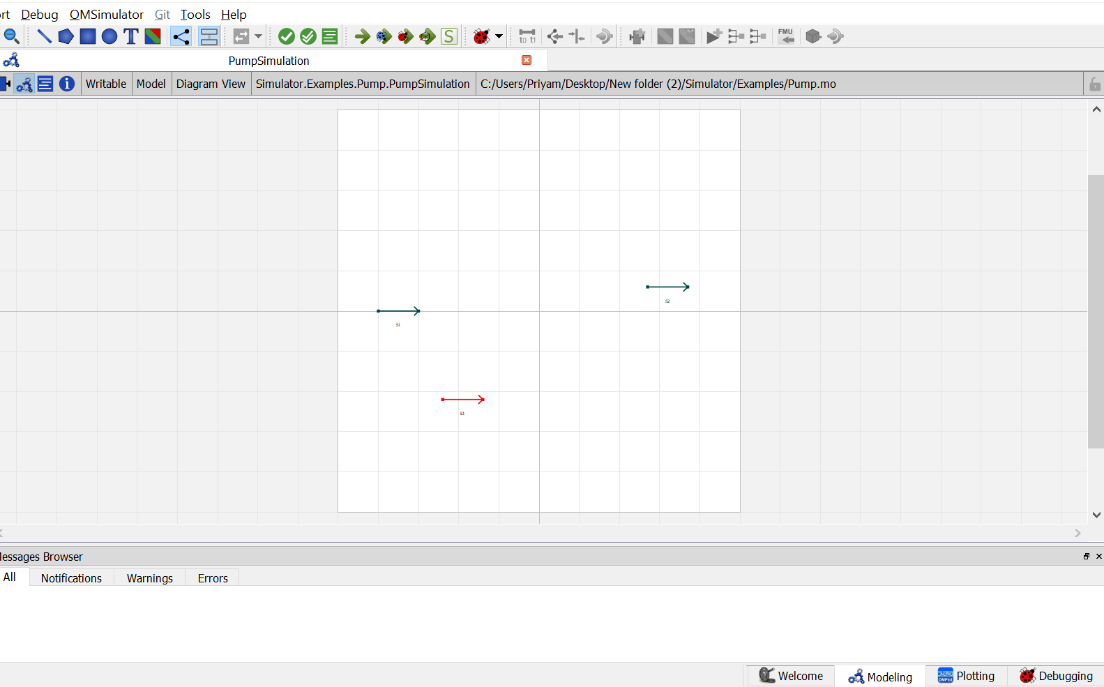
Now, Drag and drop the
CentrifugalPumpmodel available underUnitOperations. Name the instance asB1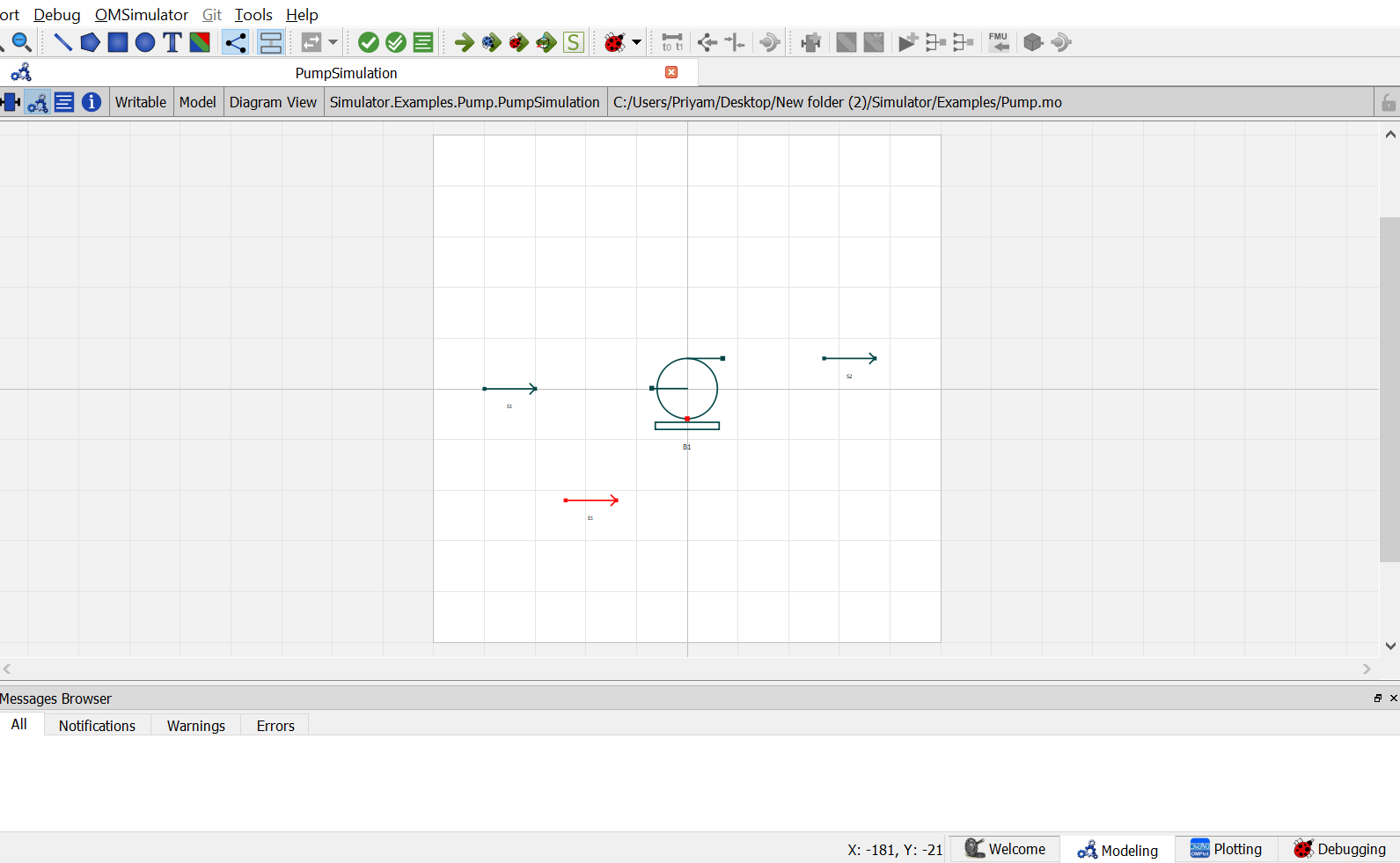
Now double click on
S1. Component Parameters window opens. Go to Stream Specifications tab. There are two parametersC and ``Ncfor which the values are to be entered. As the value forNcandCare already declared earlier in step 6 while defining the variables, these variables are directly passed here instead of the values. Repeat this for remainingoutputinstance as well.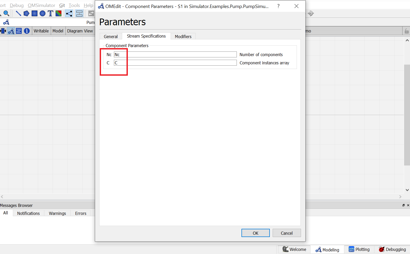
Now double click on
B1. Component Parameters window opens. Go to Pump Specifications tab and enter the values for parameters as mentioned below:
NcandCcan be entered same as material stream
Effrepresents the efficiency of the pump. Enter the value ofEffas 0.75.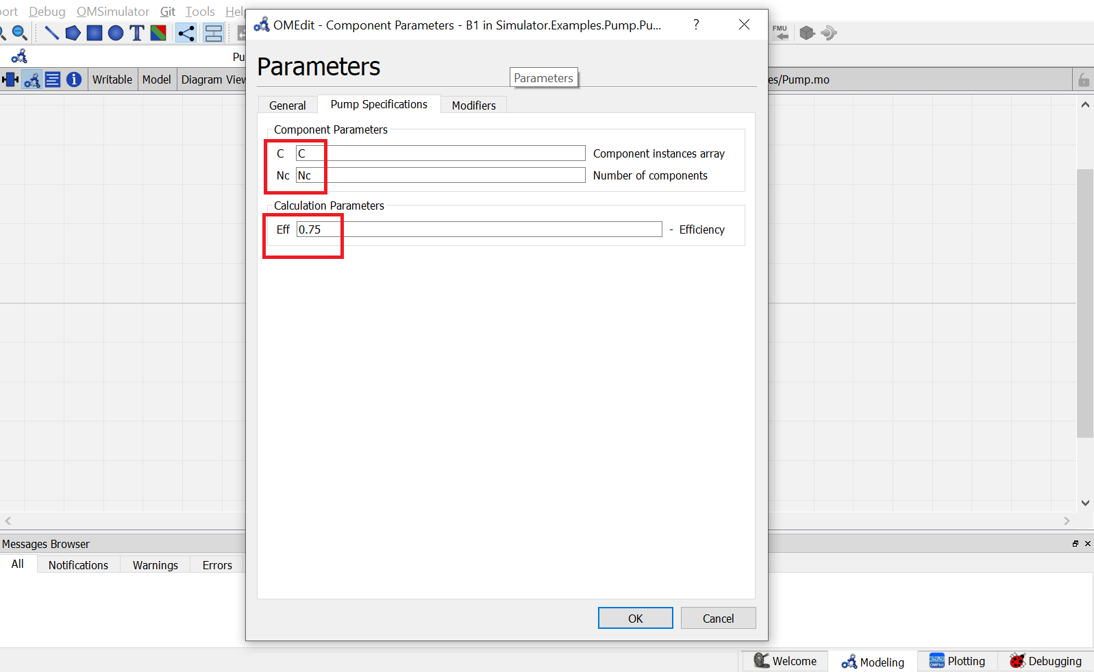
Switch to text view, following lines of code will be autogenerated
Simulator.Examples.Pump.MS S1(Nc = Nc, C = C) annotation( ...);
Simulator.UnitOperations.CentrifugalPump B1(C = C, Nc = Nc, Eff = 0.75) annotation( ...);
Simulator.Examples.Pump.MS S2(Nc = Nc, C = C) annotation( ...);
Simulator.Streams.EnergyStream E1 annotation( ...);
Now, connect the streams with unit operations. For this, switch back to Diagram view.
Switch to text view. Following lines of code will be autogenrated under
equationsectionconnect(E1.Out, B1.En) annotation( ...); connect(B1.Out, S2.In) annotation( ...); connect(S1.Out, B1.In) annotation( ...);Specify the pressure, temperature, component mole fractions and molar flow rate for the inlet material stream
S1.F_p[1] = 100;
S1.x_pc[1, :] = {0.5, 0.5};
S1.P = 101325;
S1.T = 300;
Now specify the one of the calculation variables for the pump as mentioned earlier. Here, pressure drop
Pdelis specifiedB1.Pdel = 101325;
- This completes the Pump package. Now click on
Simulatebutton to simulate thePumpSimulationmodel. Switch to Plotting Perspective to view the results.
Note
You can also find this package named
Pumpin theSimulatorlibrary underExamplespackage.
Compressor
The Adiabatic Compressor is generally used to provide energy to a vapor material stream. The energy supplied is in form of pressure.
The adiabatic compressor model have following connection ports:
Two Material Streams:
- feed stream
- outlet stream
One Energy Stream:
- power required
To simulate an adiabatic compressor, Efficiency Eff of the compressor should be provided as calculation parameter.
The variable Eff is defined as of type parameter Real.
During simulation, its value can specified directly under Compressor Specifications by double clicking on the compressor model instance.
Additionally one of the following input variables must be defined:
- Outlet Pressure
Pout- Pressure Increase
Pdel- Power Required
Q
These variables are declared of type Real. During simulation, value of one of these variables need to be defined in the equation section.