Reactors
Conversion Reactor
The Conversion Reactor is used to calculate the mole fraction of components at outlet stream when the conversion of base component for the reaction is defined.
The conversion reactor model have following connection ports:
- Two Material Streams: feed and outlet stream
- One Energy Stream: heat added
To simulate a conversion reactor, following calculation parameters must be provided:
- Calculation Mode
CalcMode- Outlet Temperature
Tdef(If calculation mode is Define_Out_Temperature)- Number of Reactions
Nr- Base Component
BC_r- Stoichiometric Coefficient of Components in Reaction
Coef_cr- Conversion of Base Component
X_r- Pressure Drop
Pdel
All the above variables are of type parameter Real except the first one (CalcMode) which is of type parameter String. It can have either of the sting values among following:
Isothermal: If the reactor is operated isothermallyDefine_Out_Temperature: If the reactor is operated at specified outlet temperatureAdiabatic: If the reactor is operated adiabatically
During simulation, their values can specified directly under Reactor Specifications by double clicking on the reactor model instance.
Simulating a Conversion Reactor
Consider the following problem statement to be simulated using Conversion Reactor:
Component System: Ethyl Acetate, Water, Acetic Acid, Ethanol
Thermodynamics: NRTL
Material Stream Information
- Molar Flow Rate: 100 mol/s
- Mole Fraction (Ethyl Acetate): 0
- Mole Fraction (Water): 0
- Mole Fraction (Acetic Acid): 0.4
- Mole Fraction (Ethanol): 0.6
- Pressure: 101325 Pa
- Temperature: 300 K
Simulate a conversion reactor where Acetic Acid reacts with Ethanol to form Ethyl Acetate and Water. The conversion of acetic acid is 30%. Assume the reactor to be operated isothermally.
Below listed points are the step by step explaination as to how to create and simulate this conversion reactor example.
Create a package named
ConversionReactor.Create a model named
MSinsideConversionReactor. This is to extendMaterialStreammodel.Extend the model
MaterialStreamand necessary property method fromThermodynamicPackagesextends Simulator.Streams.MaterialStream; extends Simulator.Files.ThermodynamicPackages.NRTL;Create another new model named
ConvReactorinsideConversionReactor. This is to extendConversionReactormodel.Extend the model
ConversionReactorfromUnitOperationspackage.extends Simulator.UnitOperations.ConversionReactor;Extend the
ConversionReactionmodel fromReactionManagerpackage available underModelsunderFilespackage.extends Simulator.Files.Models.ReactionManager.ConversionReaction;Create another new model named
ConvReactSimulationinsideConversionReactor.Similar to the
MaterialStreamexample model, importChemsepDatabaseand create variables for the compounds which are to be used fromChemsepDatabase.import data = Simulator.Files.ChemsepDatabase; parameter data.Ethylacetate etac; parameter data.Water wat; parameter data.Aceticacid aa; parameter data.Ethanol eth;Define variables for Number of components
Ncand component arrayC. Also assign the variables created for the compounds to the component array.parameter Integer Nc = 4; parameter data.GeneralProperties C[Nc] = {etac, wat, aa, eth};10. Now, create two instances of the
MaterialStreammodelMSas we require two material streams which will go as input and comes out as output. To do this, open diagram view oftestmodel, drag & dropMStwice as shown in fig. Name the instances asS1andS2.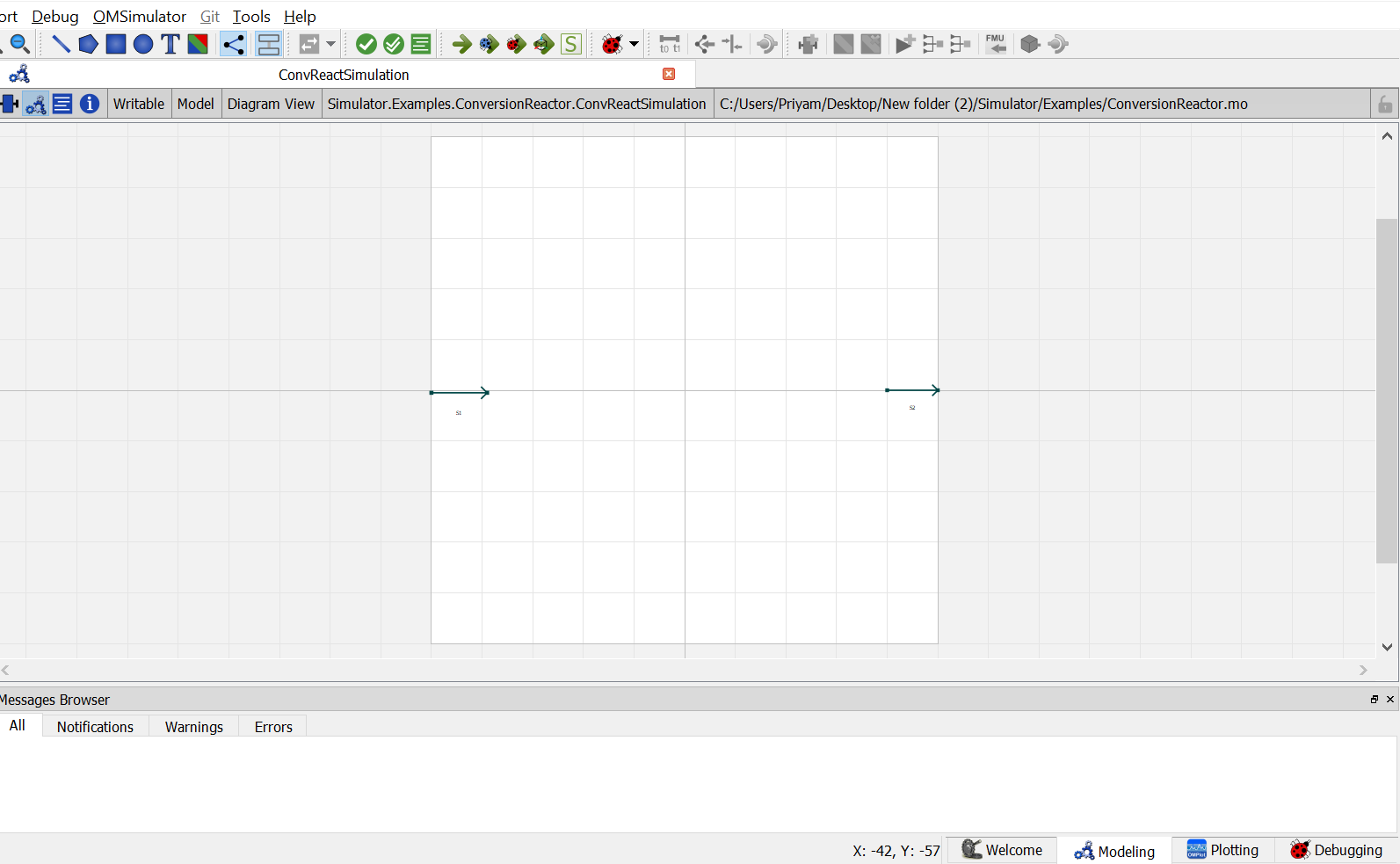
Now, create an instance of the
ConversionReactormodelconv_react. Switch to the diagram view oftestmodel, drag & dropconv_react. A pop up will appear asking the name of the component. Enter the name asB1.
12. Now double click on
S1. Component Parameters window opens. Go to Stream Specifications tab. There are two parameterNcandCfor which the values are to be entered. As the value forNcandCare already declared earlier in step 6 while defining the variables, these variables are passed here instead of the values. Repeat this for the other material stream.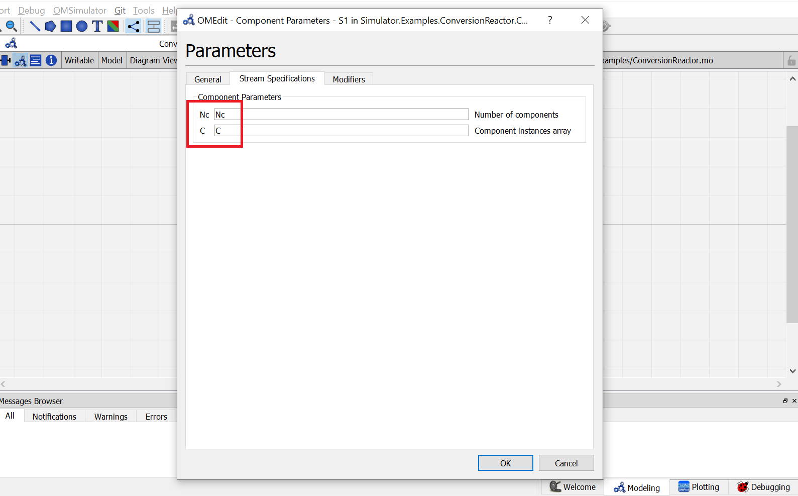
13. Now double click on
B1. Component Parameters window opens. Go to Reactor Specifications tab and enter the values for parameters as mentioned below:
NcandCcan be entered same as material stream
CalcModerepresents the operation mode for conversion reactor. Currently conversion reactor support three different modes of operation which are Isothermal,Adiabatic and Defined Outlet Temperature. As per the problem statement, Isothermal is to be used here. So enter"Isothermal".
Go to Reactions tab and enter the reaction details as mentioned below:
X{r}represents the reaction conversion. As per the problem statement enter the value as{0.3}Nrrepresents the number of reaction. Enter the value as1BC_rrepresents the base component for the reaction. Enter the corresponding component index from variableC[Nc]which represents the base component. Here, Acetic acid is the base component, so enter the value as{3}Coef_crrepresents the stoichiometric coefficients of the components in the reaction. Enter the value as{{1}, {1}, {-1}, {-1}}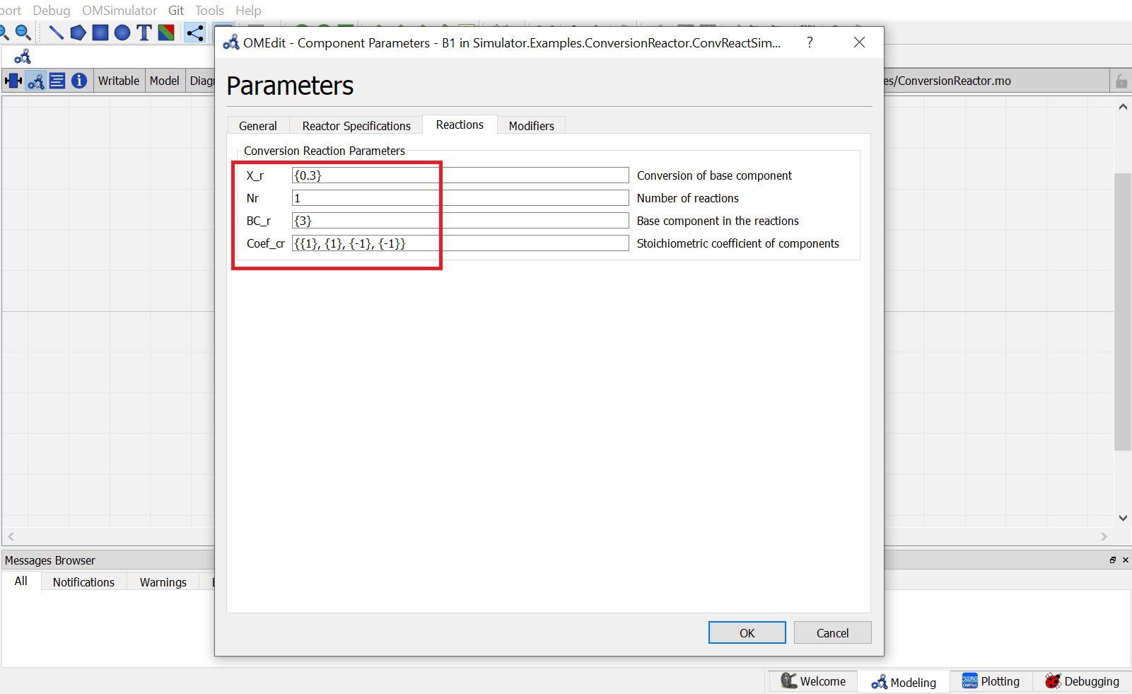
Switch to text view. Following lines of code will be autogenrated
Simulator.Examples.ConversionReactor.MS S1(Nc = Nc, C = C) annotation( ...);
Simulator.Examples.ConversionReactor.MS S2(Nc = Nc, C = C) annotation( ...);
Simulator.Examples.ConversionReactor.ConvReactor B1(Nc = Nc, C = C, Nr = 1, BC_r = {3}, Coef_cr = {{1}, {1}, {-1}, {-1}}, X_r = {0.3}, CalcMode = "Isothermal", Tdef = 300) annotation( ...);
Now, connect the streams with unit operations. For this, switch back to Diagram view.

Switch to text view. Following lines of code will be autogenrated under
equationsectionconnect(B1.Out, S2.In) annotation( ...); connect(S1.Out, B1.In) annotation( ...);Specify the pressure, temperature, component mole fractions and molar flow rate for the inlet material stream
S1.P = 101325;
S1.T = 300;
S1.x_pc[1, :] = {0, 0, 0.4, 0.6};
S1.F_p[1] = 100;
This completes the
ConversionReactorpackage. Now click onSimulatebutton to simulate theConvReactSimulationmodel. Switch to Plotting Perspective to view the results.Note
You can also find this package named
ConversionReactorin theSimulatorlibrary underExamplespackage.
Equilibrium Reactor
The Equilibrium Reactor is used to calculate the mole fraction of components at outlet stream when the equilibrium constant of the reaction is defined.
The equilibrium reactor model have following connection ports:
- Two Material Streams: feed and outlet stream
- One Energy Stream: heat added
To simulate an equilibrium reactor, following calculation parameters must be provided:
- Calculation Mode
Mode- Reaction Basis
Basis- Reaction Phase
Phase- Calculation Mode
Mode- Outlet Temperature
Tdef(If calculation mode is OutletTemperature)- Pressure Drop
Pdel- Number of Reactions
Nr- Stoichiometric Coefficient of Components in Reaction
Coef_cr- Mode of specifying Equilibrium Constant
Rmode- Equilibrium Constant
Kg(If Equilibrium Constant mode is ConstantK)- Temperature function coefficients:
A and ``B(If Equilibrium Constant mode is Tempfunc)
Among the above variables, first one CalcMode is of type parameter String. It can have either of the sting values among following:
Isothermal: If the reactor is operated isothermallyOutletTemperature: If the reactor is operated at specified outlet temperatureAdiabatic: If the reactor is operated adiabatically
Mode of specifying Equilibrium Constant Rmode is also of type parameter String. It can have either of the sting values among following:
ConstantK: If the equilibrium constant is defined directlyTempfunc: If the equilibrium constant is to be calculated from given function of temperature
The other variables are of type parameter Real. During simulation, their values can specified directly under Reactions tab by double clicking on the reactor model instance.
Simulating an Equilibrium Reactor
Consider the following problem statement to be simulated using Conversion Reactor:
Component System: Hydrogen, Carbon Monoxide, Methanol
Thermodynamics: Raoult’s Law
Material Stream Information
- Molar Flow Rate: 27.7778 mol/s
- Mole Fraction (Hydrogen): 0
- Mole Fraction (Carbon Monoxide): 0
- Mole Fraction (Methanol): 0
- Pressure: 101325 Pa
- Temperature: 366.5 K
Simulate an equilibrium reactor where Hydrogen reacts with Carbon Monoxide to form Methanol. The equilibirum constant is considered to be 0.5 and is defined on the basis of activity. Assume the reactor to be operated isothermally and the reaction to be taking place in vapor phase.
Below listed points are the step by step explaination as to how to create and simulate this equilibrium reactor example.
Create a package named
EquilibriumReactor.Create a model named
MSinsideEquilibriumReactor. This is to extendMaterialStreammodel.Extend the model
MaterialStreamand necessary property method fromThermodynamicPackagesextends Simulator.Streams.MaterialStream; extends Simulator.Files.ThermodynamicPackages.RaoultsLaw;Create another new model named
EqReactorSimulation_Ex1insideEquilibriumReactor.Similar to the
MaterialStreamexample model, importChemsepDatabaseand create variables for the compounds which are to be used fromChemsepDatabase.import data = Simulator.Files.ChemsepDatabase; parameter data.Hydrogen hyd; parameter data.Carbonmonoxide com; parameter data.Methanol meth;Define variables for Number of components
Ncand component arrayC. Also assign the variables created for the compounds to the component array.parameter Integer Nc = 3; parameter data.GeneralProperties C[Nc] = {hyd,com,meth};Now, create two instances of the
MaterialStreammodelMSas we require two material streams which will go as input and comes out as output. To do this, open diagram view ofEqReactorSimulation_Ex1model, drag & dropMStwice as shown in fig. Name the instances asS1andS2.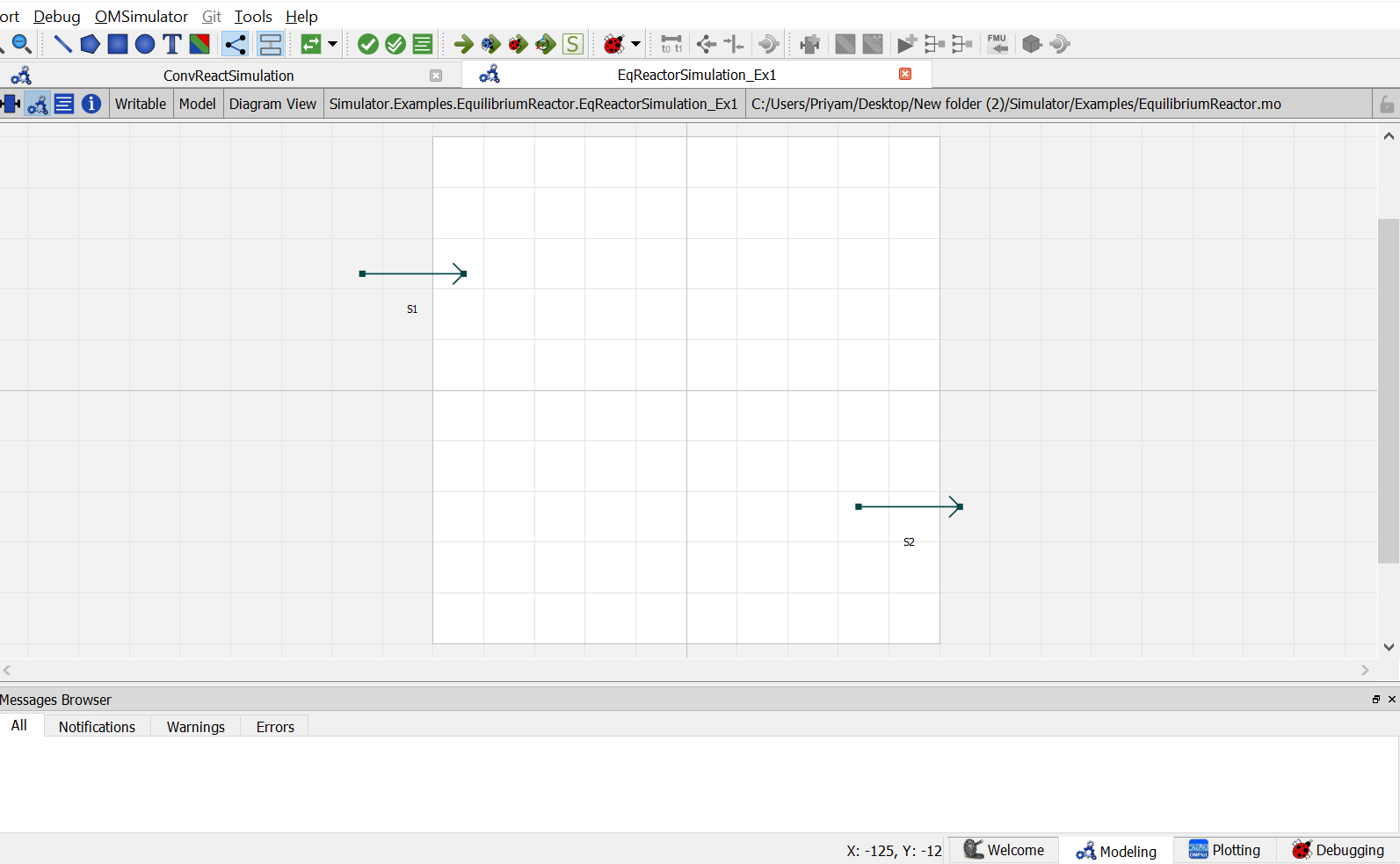
Now, Drag and drop the
EquilibriumReactormodel available underUnitOperations. Name the instance asEqreactor.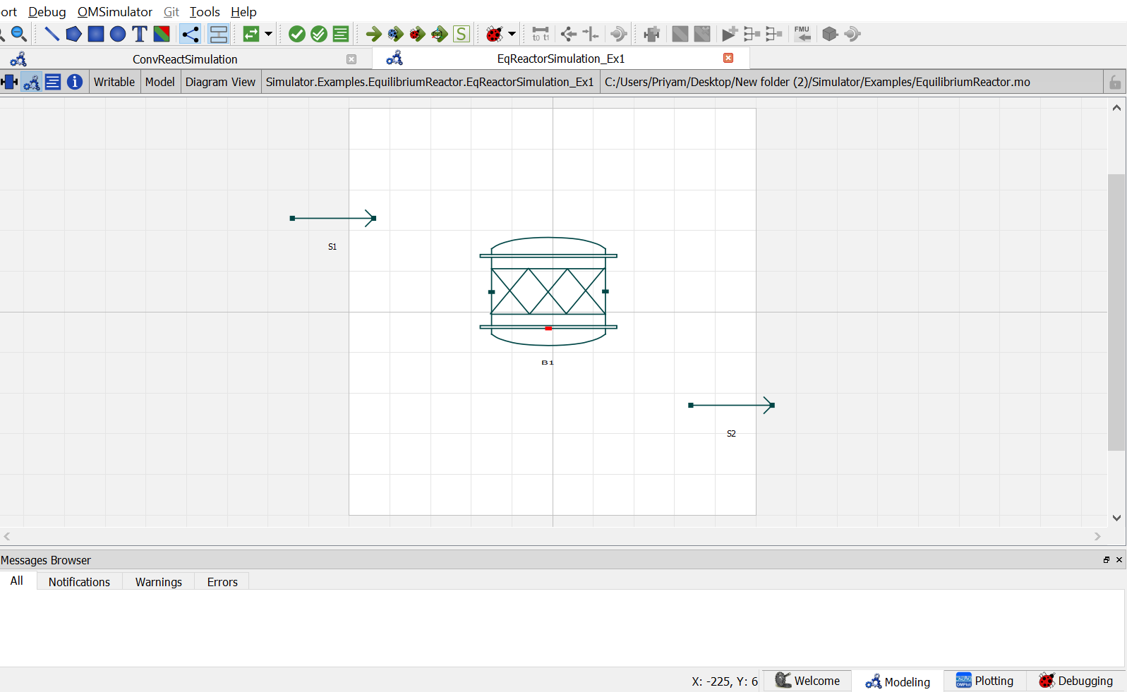
9. Now double click on
Inlet. Component Parameters window opens. Go to Stream Specifications tab. There are two parameterNcandCfor which the values are to be entered. As the value forNcandCare already declared earlier in step 6 while defining the variables, these variables are passed here instead of the values. Repeat this for the other material stream.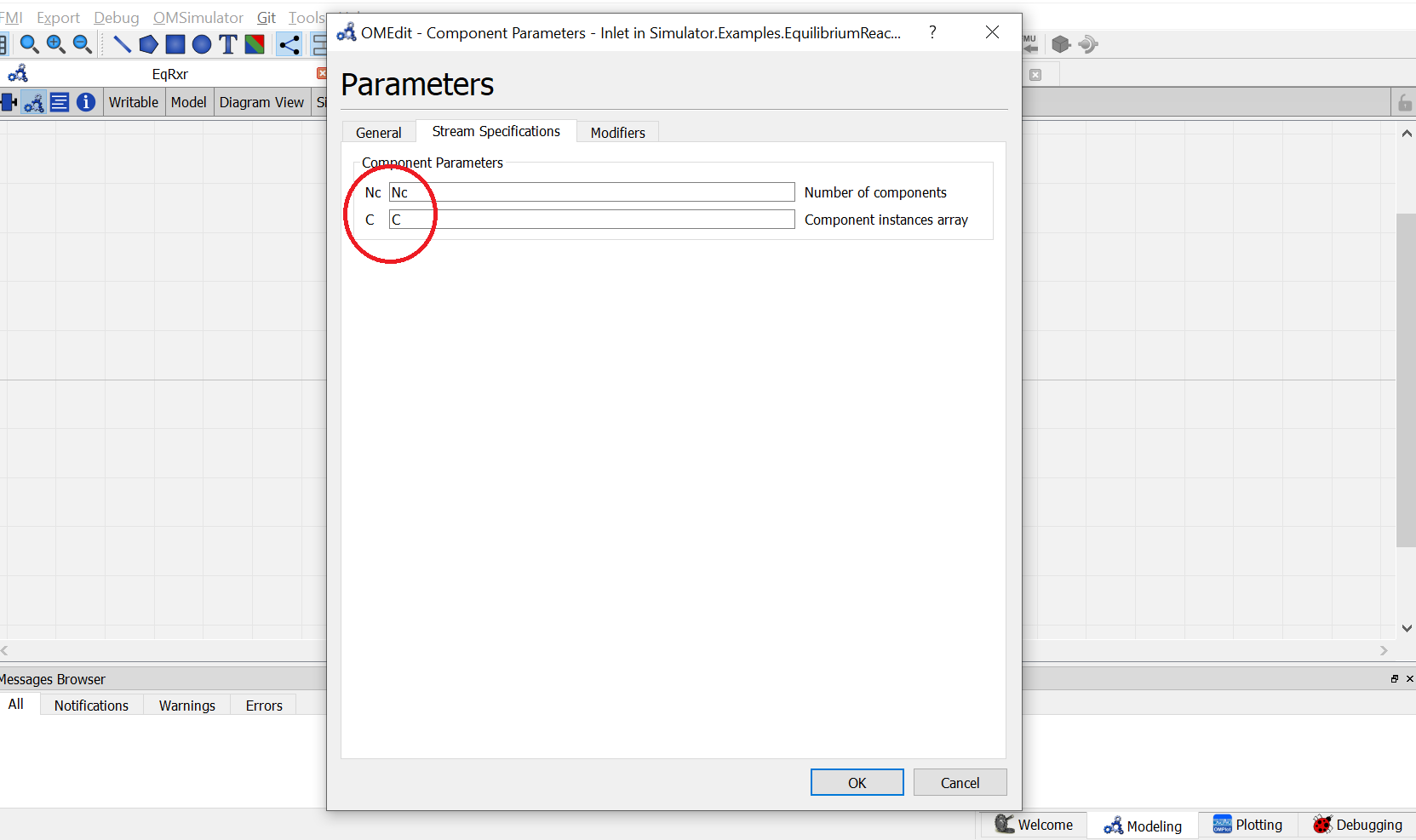
10. Now double click on
B1. Component Parameters window opens. Go to Reactor Specifications tab and enter the values for parameters as mentioned below:
NcandCcan be entered same as material stream
CalcModerepresents the operation mode for equilibrium reactor. Currently, equilibrium reactor support three different modes of operation which are Isothermal,Adiabatic and Defined Outlet Temperature. As per the problem statement, Isothermal is to be used here. So enter"Isothermal".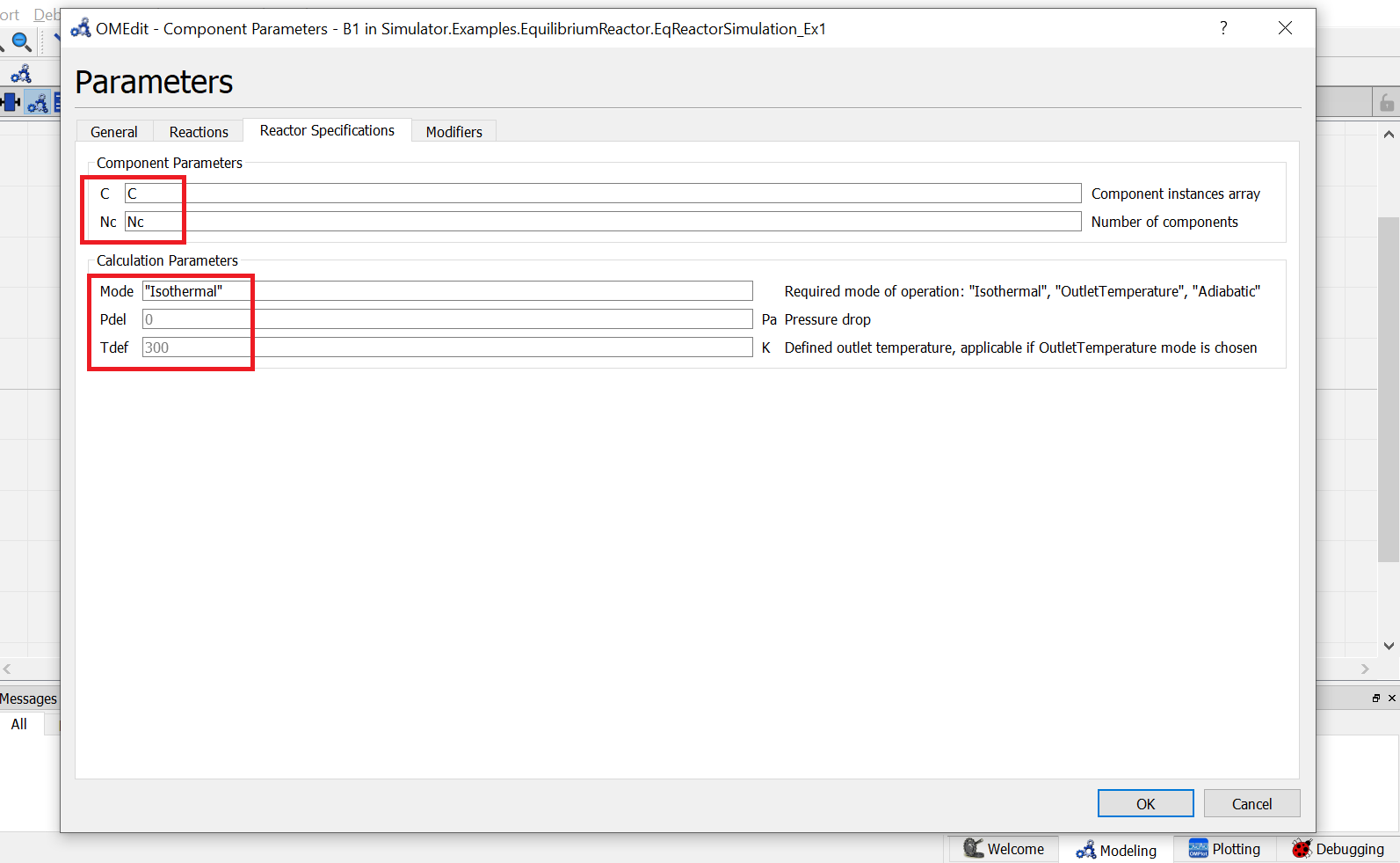
Go to Reactions tab and enter the reaction details as mentioned below:
Phaserepresents the reaction phase. Currently, the equilibrium reactor support two phases: vapour and liquid. As per the problem statement, it’s a vapour phase reaction. So enter thePhaseasVapour.Basisrepresents the basis on which the equilibrium constant is defined. Currently, the equilibrium reactor support three basis: activity, mole fraction and partial pressure. As per the problem statement, the equilibrium constant is defined on basis of activity. SO enter theBasisasActivity.Coef_crrepresents the stoichiometric coefficients of the components in the reaction. Enter the value as{{1}, {1}, {-1}, {-1}}.Rmoderepresents the different modes by which the equilibrium constant an be defined. Currently, equilibrium reactor supports two modes: Constant K and K as a function of temperature. As per the problem statement, equilibirum constant value is given. So enterRmodeasConstantK.Kgrepresents the equilibrium constant value. Enter the value as{0.5}.
Switch to text view. Following lines of code will be autogenrated
Simulator.Examples.EquilibriumReactor.MS S1(Nc = Nc, C = C) annotation( ...);
Simulator.Examples.EquilibriumReactor.MS S2(Nc = Nc, C = C) annotation( ...);
Simulator.UnitOperations.EquilibriumReactor B1(Basis = "Activity",C = C, Coef_cr = {{-2}, {-1}, {1}}, Kg = {0.5}, Mode = "Isothermal", Nc = Nc, Phase = "Vapour", Rmode = "ConstantK") annotation( ...);
Now, connect the streams with unit operations. For this, switch back to Diagram view.

Switch to text view. Following lines of code will be autogenrated under
equationsectionconnect(S1.Out, B1.In) annotation( ...); connect(B1.Out, S2.In) annotation( ...);Specify the pressure, temperature, component mole fractions and molar flow rate for the inlet material stream
S1.T = 366.5;
S1.P = 101325;
S1.F_p[1] = 27.7778;
S1.x_pc[1, :] = {0.667,0.333,0};
This completes the
EquilibriumReactorpackage. Now click onSimulatebutton to simulate theEqReactorSimulation_Ex1model. Switch to Plotting Perspective to view the results.Note
You can also find this example named
EquilibriumReactorin theSimulatorlibrary underExamplespackage.
Plug Flow Reactor
The Plug Flow Reactor (PFR) is used to calculate the mole fraction of components at outlet stream when the reaction kinetics is defined.
The plug flow reactor model have following connection ports:
- Two Material Streams: feed and outlet stream
- One Energy Stream: heat added
To simulate a plug flow reactor, following calculation parameters must be provided:
- Calculation Mode
Mode- Reaction Basis
Basis- Reaction Phase
Phase- Outlet Temperature
Tdef(If calculation mode is Define Outlet Temperature)- Number of Reactions
Nr- Base Component
Base_C- Stoichiometric Coefficient of Components in Reaction
Coef_cr- Reaction Order
DO_cr- Pre-exponential Factor
Af_r- Activation Energy
Ef_r- Pressure Drop
Pdel
Among the above variables, first three variables are of type parameter String. First one, Calculation Mode Mode can have either of the sting values among the following:
Isothermal: If the reactor is operated isothermallyDefine Outlet Temperature: If the reactor is operated at specified outlet temperatureAdiabatic: If the reactor is operated adiabatically
Second one, Reaction Basis Basis can have either of the string values among the following:
Molar Concentration: If the reaction rate is defined in terms of Molar ConcentrationMass Concentration: If the reaction rate is defined in terms of Mass ConcentrationMolar Fractions: If the reaction rate is defined in terms of Molar FractionsMass Fractions: If the reaction rate is defined in terms of Mass Fractions
Third one, Reaction Phase Phase, can have either of the string values among the following:
Mixture: If the reaction is a mixed phase reactionLiquid: If the reaction is a liquid phase reactionVapour: If the reaction is a vapour phase reaction
The other variables are of type parameter Real. During simulation, their values can specified directly under Reactor Specifications and Reactions by double clicking on the PFR model instance.
Simulating a Plug Flow Reactor
Consider the following problem statement to be simulated using Conversion Reactor:
Component System: Hydrogen, Carbon Monoxide, Methanol
Thermodynamics: Raoult’s Law
Material Stream Information
- Molar Flow Rate: 27.7778 mol/s
- Mole Fraction (Hydrogen): 0
- Mole Fraction (Carbon Monoxide): 0
- Mole Fraction (Methanol): 0
- Pressure: 101325 Pa
- Temperature: 366.5 K
Simulate an equilibrium reactor where Hydrogen reacts with Carbon Monoxide to form Methanol. The equilibirum constant is considered to be 0.5 and is defined on the basis of activity. Assume the reactor to be operated isothermally and the reaction to be taking place in vapor phase.
Below listed points are the step by step explaination as to how to create and simulate this equilibrium reactor example.
Create a package named
PFR.Create a model named
MSinsidePFR. This is to extendMaterialStreammodel.Extend the model
MaterialStreamand necessary property method fromThermodynamicPackagesextends Simulator.Streams.MaterialStream; extends Simulator.Files.ThermodynamicPackages.RaoultsLaw;Create another new model named
PFRSimulationinsidePFR.Similar to the
MaterialStreamexample model, importChemsepDatabaseand create variables for the compounds which are to be used fromChemsepDatabase.import data = Simulator.Files.ChemsepDatabase; parameter data.Ethyleneoxide eth; parameter data.Ethyleneglycol eg; parameter data.Water wat;Define variables for Number of components
Ncand component arrayC. Also assign the variables created for the compounds to the component array.parameter Integer Nc = 3; parameter data.GeneralProperties C[Nc] = {eth, wat, eg};Now, create two instances of the
MaterialStreammodelMSas we require two material streams which will go as input and comes out as output. To do this, open diagram view ofPFRSimulation` model, drag & drop ``MStwice as shown in fig. Name the instances asS1andS2.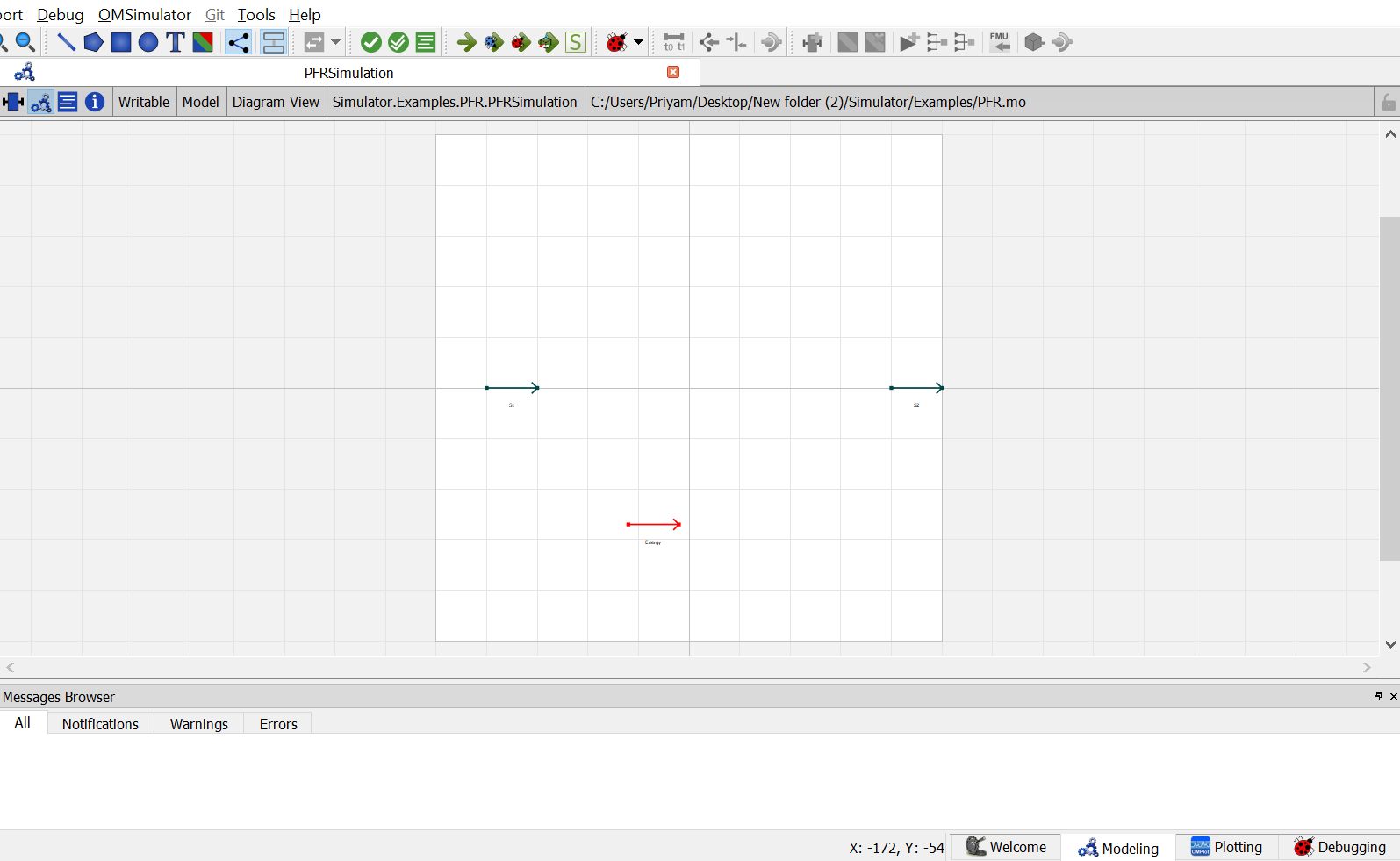
Now, Drag and drop the
PFRmodel available underPFRpackage underUnitOperations. Name the instance asB1.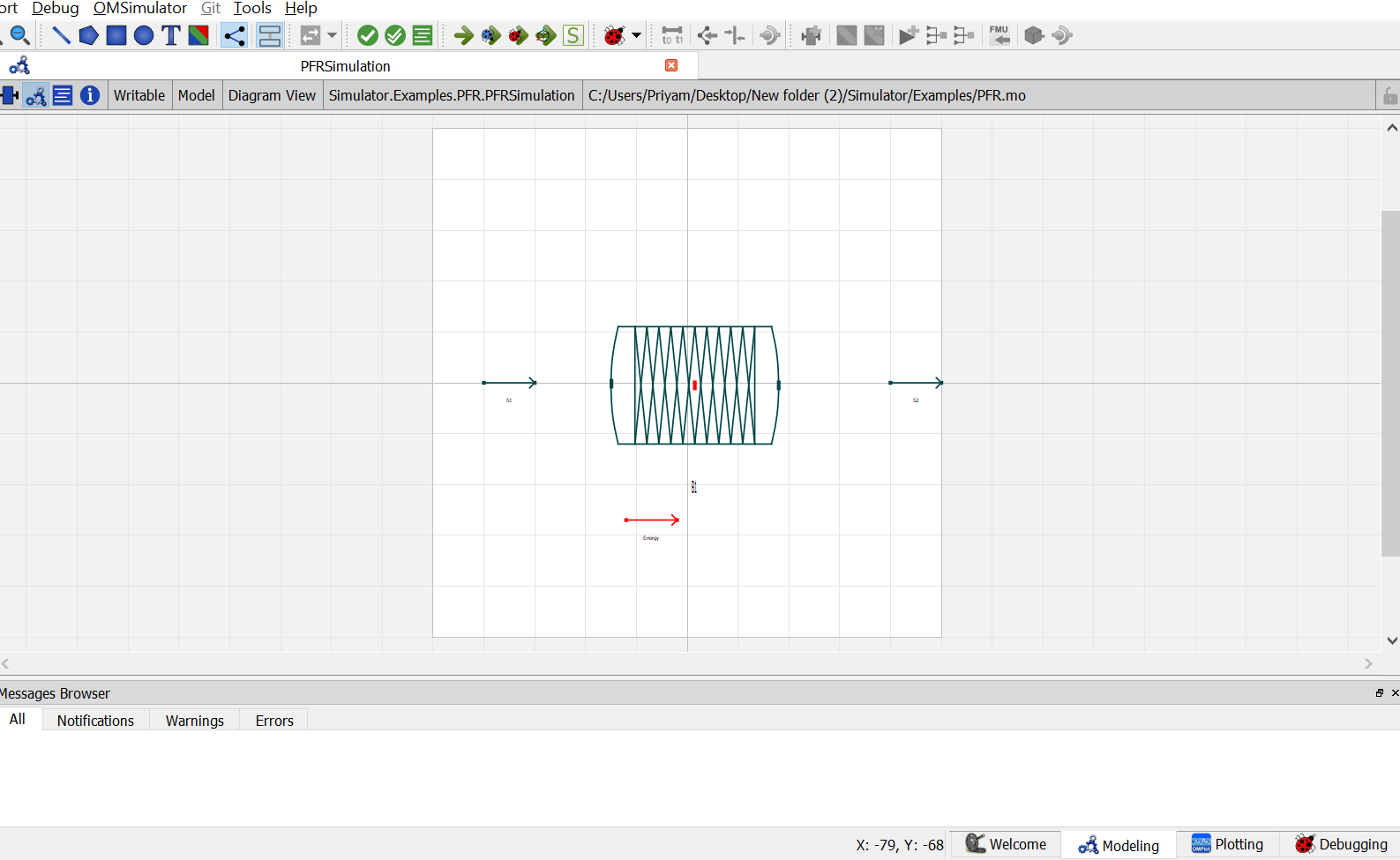
9. Now double click on
S1. Component Parameters window opens. Go to Stream Specifications tab. There are two parameterNcandCfor which the values are to be entered. As the value forNcandCare already declared earlier in step 6 while defining the variables, these variables are passed here instead of the values. Repeat this for the other material stream.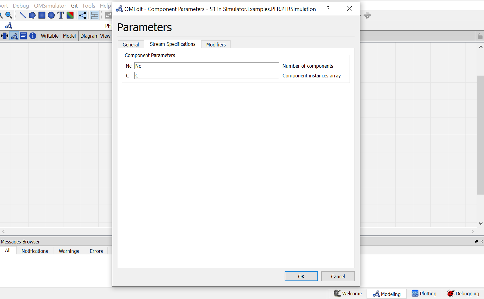
10. Now double click on
B1. Component Parameters window opens. Go to Reactor Specifications tab and enter the values for parameters as mentioned below:
NcandCcan be entered same as material stream
Moderepresents the operation mode for equilibrium reactor. Currently, plug flow reactor support three different modes of operation which are Isothermal,Adiabatic and Defined Outlet Temperature. As per the problem statement, Isothermal is to be used here. So enter"Isothermal".
Pdelrepresents the pressure drop across the PFR. Enter the value as90.65.
Go to Reactions tab and enter the reaction details as mentioned below:
Phaserepresents the reaction phase. Currently, the equilibrium reactor support two phases: vapour and liquid. As per the problem statement, it’s a vapour phase reaction. So enter thePhaseasVapour.Basisrepresents the basis on which the equilibrium constant is defined. Currently, the equilibrium reactor support three basis: activity, mole fraction and partial pressure. As per the problem statement, the equilibrium constant is defined on basis of activity. SO enter theBasisasActivity.Nrrepresents the number of reactions. Enter the value as1.Bc_rrepresents the base component of the reaction.Coef_crrepresents the stoichiometric coefficients of the components in the reaction. Enter the value as{{1}, {1}, {-1}, {-1}}.Rmoderepresents the different modes by which the equilibrium constant an be defined. Currently, equilibrium reactor supports two modes: Constant K and K as a function of temperature. As per the problem statement, equilibirum constant value is given. So enterRmodeasConstantK.Kgrepresents the equilibrium constant value. Enter the value as{0.5}.Switch to text view. Following lines of code will be autogenrated
Simulator.Examples.EquilibriumReactor.ms Inlet(Nc = Nc, C = C) annotation( ...);
Simulator.Examples.EquilibriumReactor.ms Outlet(Nc = Nc, C = C) annotation( ...);
Simulator.UnitOperations.EquilibriumReactor Eqreactor(Basis = "Activity",C = C, Coef_cr = {{-2}, {-1}, {1}}, Kg = {0.5}, Mode = "Isothermal", Nc = Nc, Phase = "Vapour", Rmode = "ConstantK") annotation( ...);
Now, connect the streams with unit operations. For this, switch back to Diagram view.
Switch to text view. Following lines of code will be autogenrated under
equationsectionconnect(Inlet.Out, Eqreactor.In) annotation( ...); connect(Eqreactor.Out, Outlet.In) annotation( ...);Specify the pressure, temperature, component mole fractions and molar flow rate for the inlet material stream
Inlet.T = 366.5;
Inlet.P = 101325;
Inlet.F_p[1] = 27.7778;
Inlet.x_pc[1, :] = {0.667,0.333,0};
- This completes the
EquilibriumReactorpackage. Now click onSimulatebutton to simulate theEqRxrmodel. Switch to Plotting Perspective to view the results.Note
You can also find this example named
EquilibriumReactorin theSimulatorlibrary underExamplespackage.