Exchangers
Heater
The Heater is used to simulate the heating process of a material stream.
The heater model have following connection ports:
- Two Material Streams: feed and outlet stream
- One Energy Stream: heat added
Following calculation parameters must be provided to the heater:
- Pressure Drop
Pdel- Efficiency
Eff
The above variables have been declared of type parameter Real. During simulation, their values can specified directly under Heater Specifications by double clicking on the heater model instance.
In addition to the above parameters, any one additional variable from the below list must be provided for the model to simulate successfully:
- Outlet Temperature
Tout- Temperature Increase
Tdel- Heat Added
Q- Outlet Stream Vapor Phase Mole Fraction
xvapout
These variables are declared of type Real. During simulation, value of one of these variables need to be defined in the equation section.
Simulating a Heater
Create a package named
HeaterCreate a model named
MSinsideHeater. This is to extendMaterialStreammodelExtend the model
MaterialStreamand necessary property method fromThermodynamicPackagesextends Simulator.Streams.MaterialStreams; extends Simulator.Files.ThermodynamicPackages.RaoultsLaw;Create another new model named
HeaterSimulationSimilar to the
MaterialStreamexample model, importChemsepDatabaseand create variables for the compounds which are to be used fromChemsepDatabaseimport data = Simulator.Files.ChemsepDatabase; parameter data.Methanol meth; parameter data.Ethanol eth; parameter data.Water wat;Define variables for Number of components
Ncand component arrayC. Also assign the variables created for the compounds to the component arrayparameter Integer Nc = 3; parameter data.GeneralProperties C[Nc] = {meth, eth, wat};Now, create three instances of the
MaterialStreammodelMSas we require one material stream which will go as input and two material streams which will come as output. To do this, open diagram view ofHeaterSimulationmodel, drag & dropMSteice as shown in fig. Name the instances asS1andS2.
Now, drag and drop the
Heatermodel available underUnitOperations. Name the instance asB1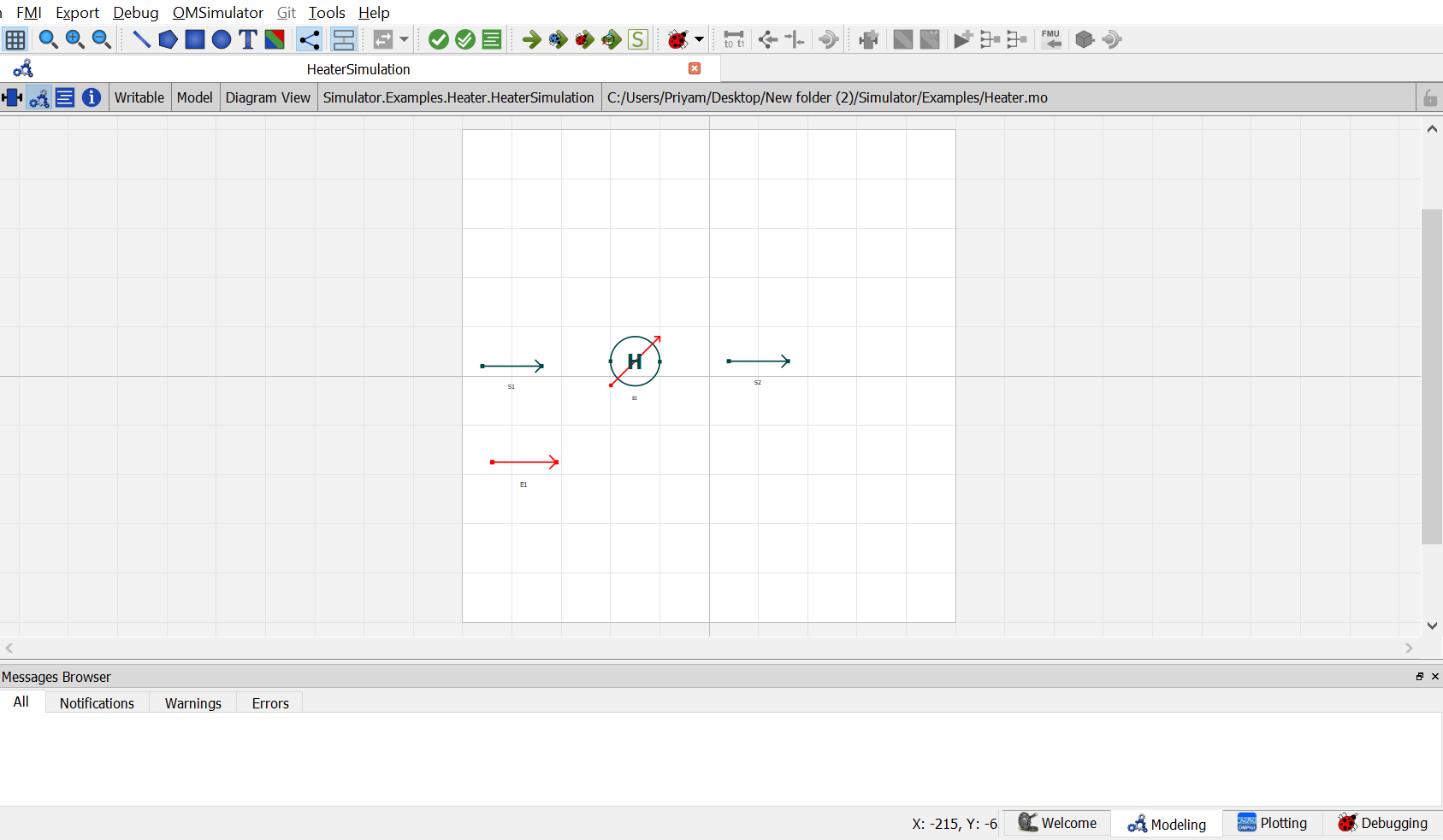
Now, drag and drop the
EnergyStreammodel available underStreams. name the instance asE1.Now double click on
S1. Component Parameters window opens. Go to Stream Specifications tab. There are two parameterNcandCfor which the values are to be entered. As the value forNcandCare already declared earlier in step 6 while defining the variables, these variables are passed here instead of the values. Repeat this for the other material streams.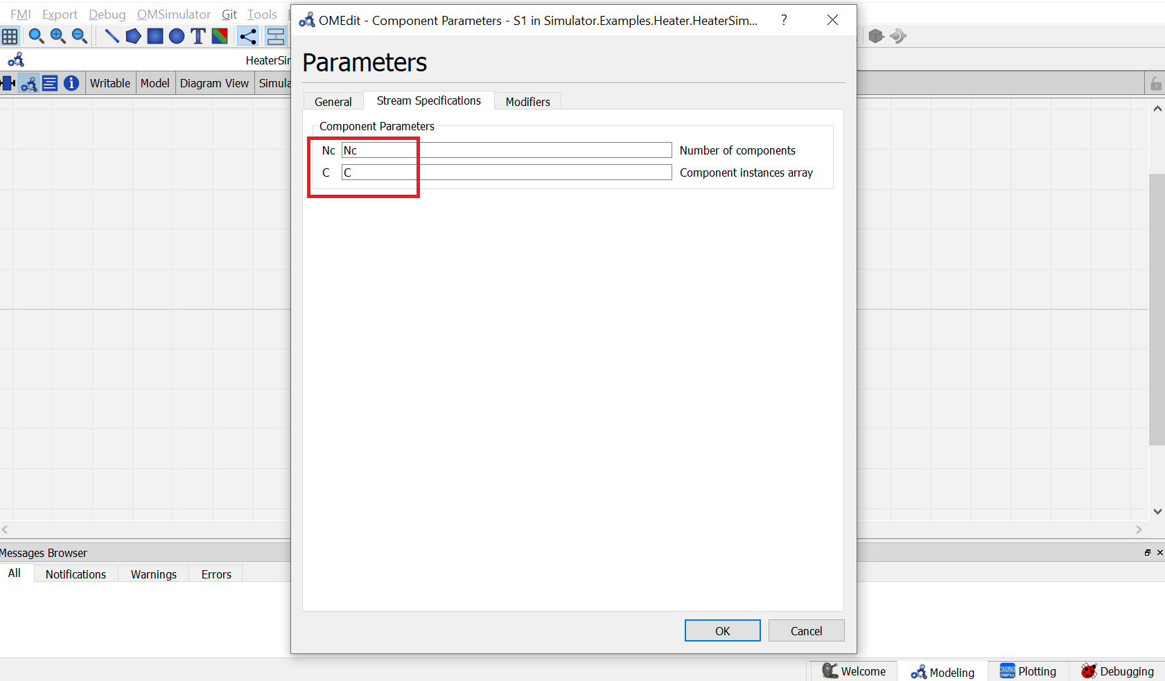
Now double click on
B1. Component Parameters window opens. Go to Heater Specifications tab and enter the values for parameters as mentioned below:
NcandCcan be entered same as material stream
Pdelrepresents the pressure drop across the heater. As per the problem statement, enterPdelas101325.
Effrepresents the heater efficiency. As per the problem statement, enterEffas1.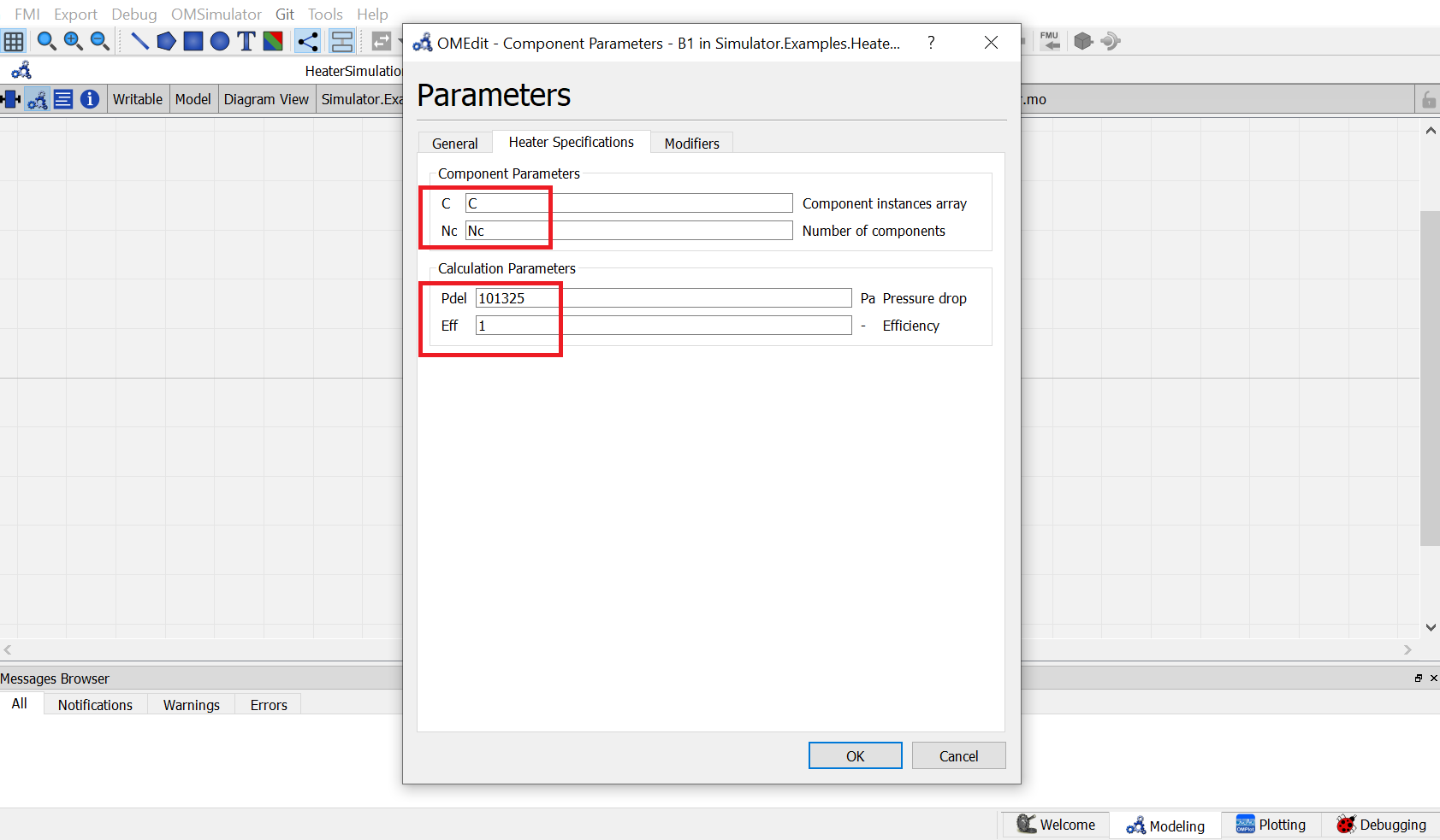
Switch to text view. Following lines of code will be autogenrated
Simulator.Examples.Heater.MS S1(Nc = Nc, C = C) annotation( ...);
Simulator.Examples.Heater.MS S2(Nc = Nc, C = C) annotation( ...);
Simulator.UnitOperations.Heater B1(C = C, Eff = 1, Nc = Nc, Pdel = 101325)  annotation( ...);
Simulator.Streams.EnergyStream E1 annotation ( ...);
Now, connect the streams with unit operations. For this, switch back to Diagram view.
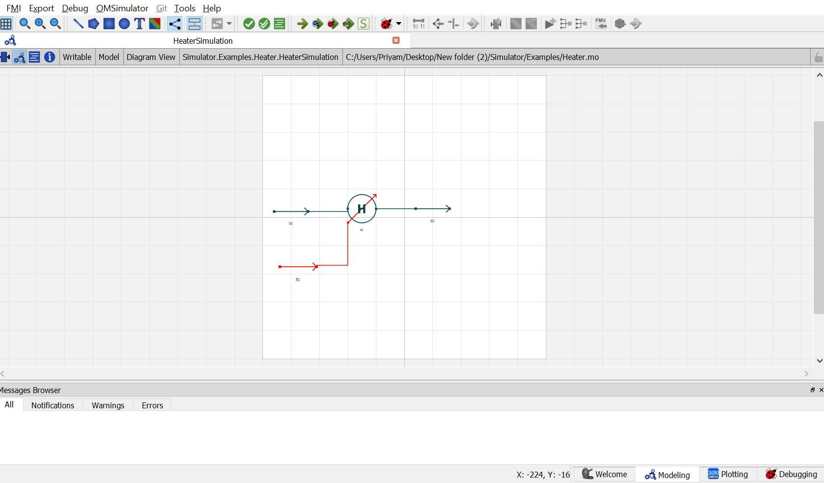
Switch to text view. Following lines of code will be autogenrated under
equationsectionconnect(E1.Out, B1.En) annotation( ...); connect(B1.Out, S2.In) annotation( ...); connect(S1.Out, B1.In) annotation( ...);Specify the pressure, temperature, component mole fractions and molar flow rate for the inlet material stream
S1.x_pc[1, :] = {0.33, 0.33, 0.34};
S1.P = 202650;
S1.T = 320;
S1.F_p[1] = 100;
Now specify one of the variables mentioned earlier during model explaination to satisfy the degrees of freedom. As per the problem statement, amount of heat added is to be specified.
B1.Q = 2000000;This completes the Heater package. Now click on
Simulatebutton to simulate theHeaterSimulationmodel. Switch to Plotting Perspective to view the results.Note
You can also find this package named
Heaterin theSimulatorlibrary underExamplespackage.
Cooler
The Cooler is used to simulate the cooling process of a material stream.
The cooler model have following connection ports:
- Two Material Streams: feed and outlet stream
- One Energy Stream: heat added
Following calculation parameters must be provided to the cooler:
- Pressure Drop
Pdel- Efficiency
Eff
The above variables have been declared of type parameter Real. During simulation, their values can specified directly under Cooler Specifications by double clicking on the cooler model instance.
In addition to the above parameters, any one additional variable from the below list must be provided for the model to simulate successfully:
- Outlet Temperature
Tout- Temperature Drop
Tdel- Heat Removed
Q- Outlet Stream Vapor Phase Mole Fraction
xvapout
These variables are declared of type Real. During simulation, value of one of these variables need to be defined in the equation section.
Simulating a Cooler
Create a package named
CoolerCreate a model named
MSinsideHeater. This is to extendMaterialStreammodelExtend the model
MaterialStreamand necessary property method fromThermodynamicPackagesextends Simulator.Streams.MaterialStreams; extends Simulator.Files.ThermodynamicPackages.RaoultsLaw;Create another new model named
CoolerSimulationSimilar to the
MaterialStreamexample model, importChemsepDatabaseand create variables for the compounds which are to be used fromChemsepDatabaseimport data = Simulator.Files.ChemsepDatabase; parameter data.Methanol meth; parameter data.Ethanol eth; parameter data.Water wat;Define variables for Number of components
Ncand component arrayC. Also assign the variables created for the compounds to the component arrayparameter Integer Nc = 3; parameter data.GeneralProperties C[Nc] = {meth, eth, wat};Now, create three instances of the
MaterialStreammodelMSas we require one material stream which will go as input and two material streams which will come as output. To do this, open diagram view ofHeaterSimulationmodel, drag & dropMSteice as shown in fig. Name the instances asS1andS2.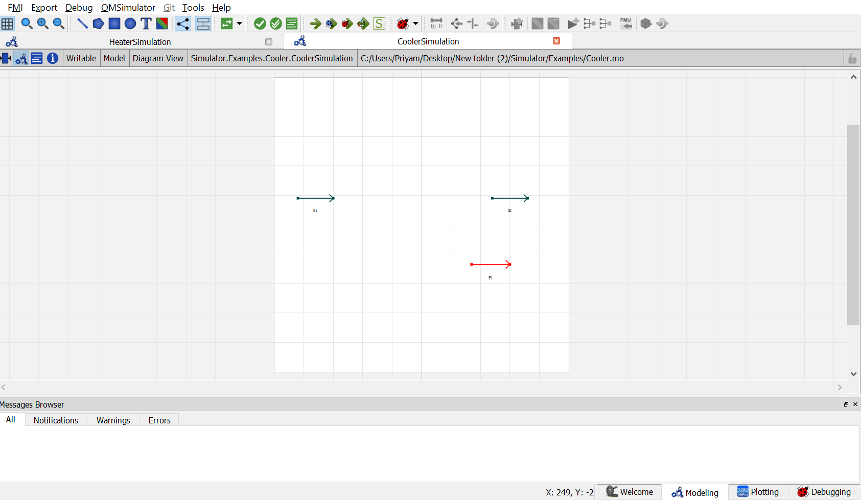
Now, drag and drop the
Coolermodel available underUnitOperations. Name the instance asB1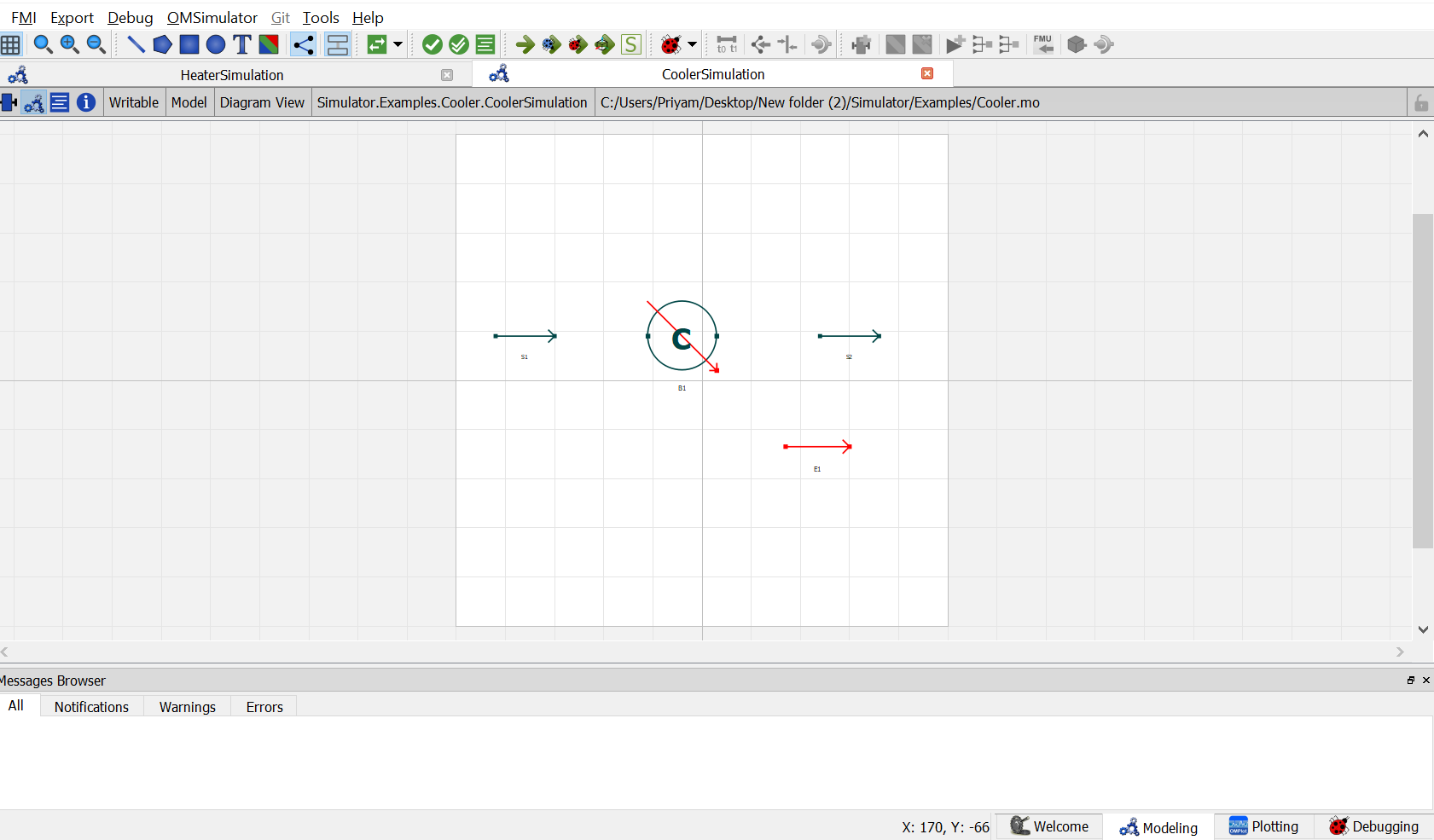
Now, drag and drop the
EnergyStreammodel available underStreams. name the instance asE1.Now double click on
S1. Component Parameters window opens. Go to Stream Specifications tab. There are two parameterNcandCfor which the values are to be entered. As the value forNcandCare already declared earlier in step 6 while defining the variables, these variables are passed here instead of the values. Repeat this for the other material streams.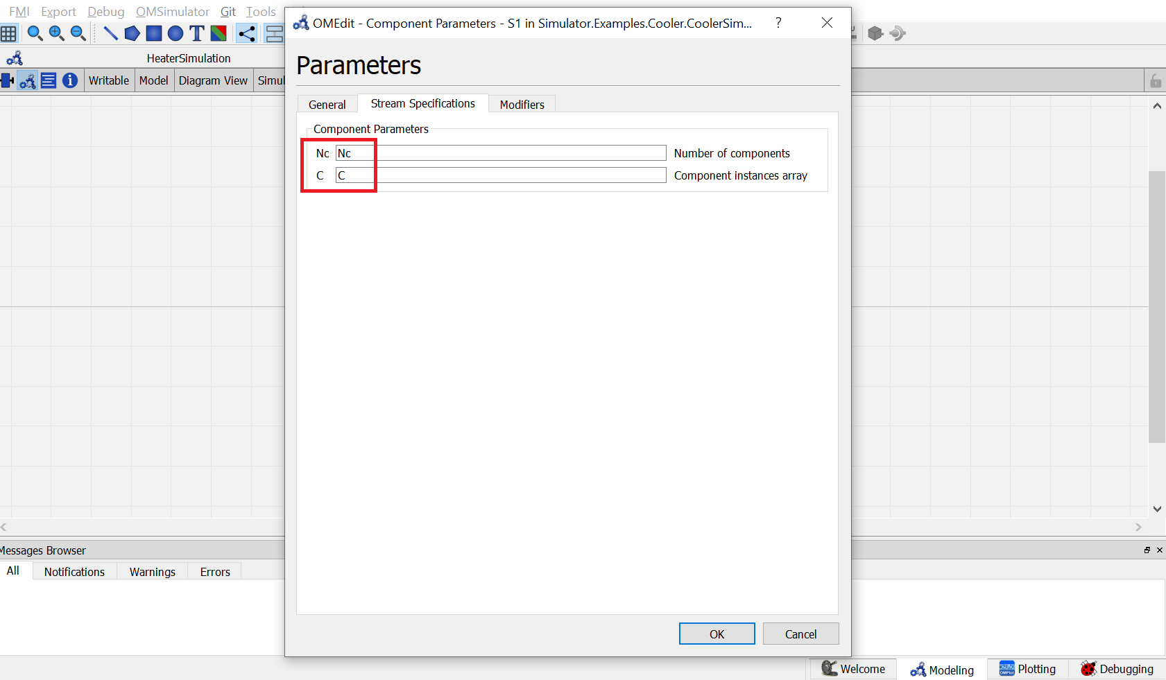
Now double click on
B1. Component Parameters window opens. Go to Heater Specifications tab and enter the values for parameters as mentioned below:
NcandCcan be entered same as material stream
Pdelrepresents the pressure drop across the cooler. As per the problem statement, enterPdelas0.
Effrepresents the cooler efficiency. As per the problem statement, enterEffas1.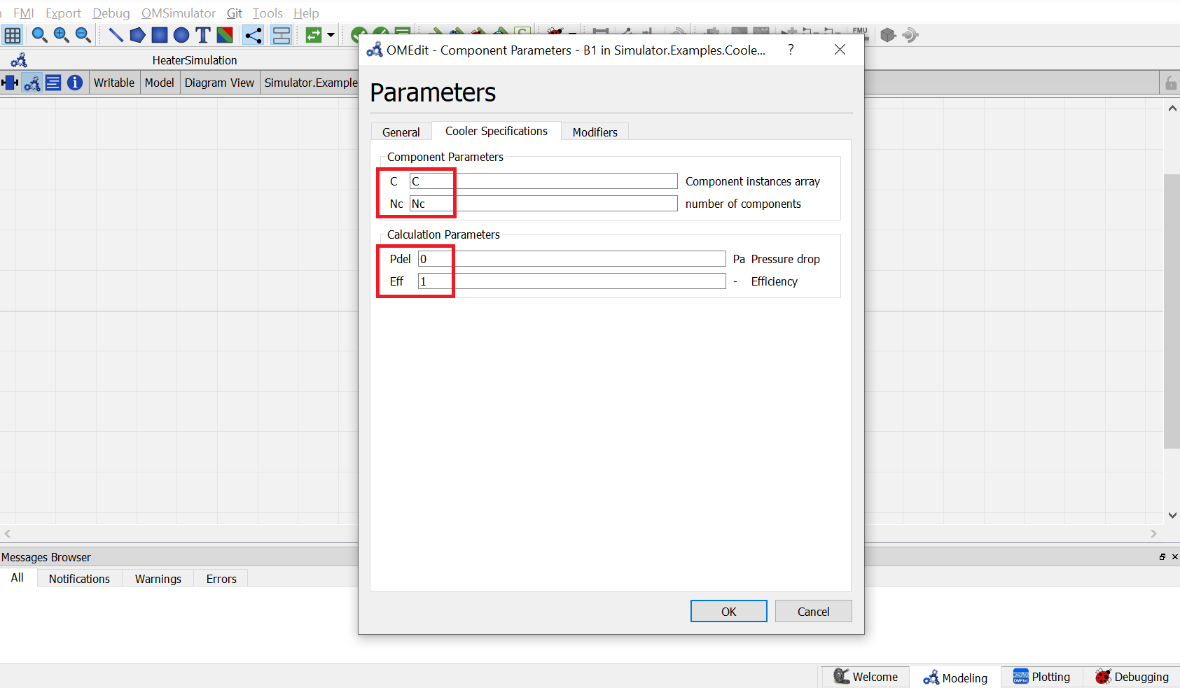
Switch to text view. Following lines of code will be autogenrated
Simulator.Examples.Heater.MS S1(Nc = Nc, C = C) annotation( ...);
Simulator.Examples.Heater.MS S2(Nc = Nc, C = C) annotation( ...);
Simulator.UnitOperations.Cooler B1(Pdel = 0, Eff = 1, Nc = Nc, C = C)  annotation( ...);
Simulator.Streams.EnergyStream E1 annotation ( ...);
Now, connect the streams with unit operations. For this, switch back to Diagram view.

Switch to text view. Following lines of code will be autogenrated under
equationsectionconnect(E1.Out, B1.En) annotation( ...); connect(B1.Out, S2.In) annotation( ...); connect(S1.Out, B1.In) annotation( ...);Specify the pressure, temperature, component mole fractions and molar flow rate for the inlet material stream
S1.x_pc[1, :] = {0.33, 0.33, 0.34};
S1.P = 101325;
S1.T = 353;
S1.F_p[1] = 100;
Now specify one of the variables mentioned earlier during model explaination to satisfy the degrees of freedom. As per the problem statement, amount of heat removed is to be specified.
B1.Q = 2000000;This completes the Cooler package. Now click on
Simulatebutton to simulate theCoolerSimulationmodel. Switch to Plotting Perspective to view the results.Note
You can also find this package named
Coolerin theSimulatorlibrary underExamplespackage.